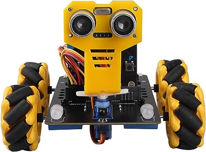
Smart Mecanum Wheel Robot
|
||
Quick Start of Smart Mecanum Wheel Robot
Download of micro:bit program
First, connect one end of the USB cable with computer or tablet, and the other end connects with the micro:bit mainboard.
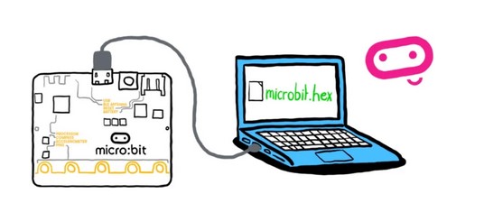
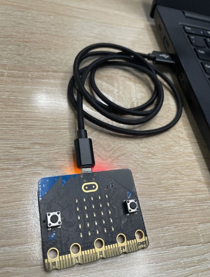
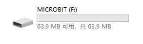
Then, there will be a MICROBIT disk in the computer as shown below.
Copy the file “QuickStart.hex” into MICROBIT disk, and then we have finished the download of micro:bit program.
http://wiki2.haljia.com/download/microbit/smartrobot_mecanum/quickstart.hex
Installation of smart Mecanum wheel robot
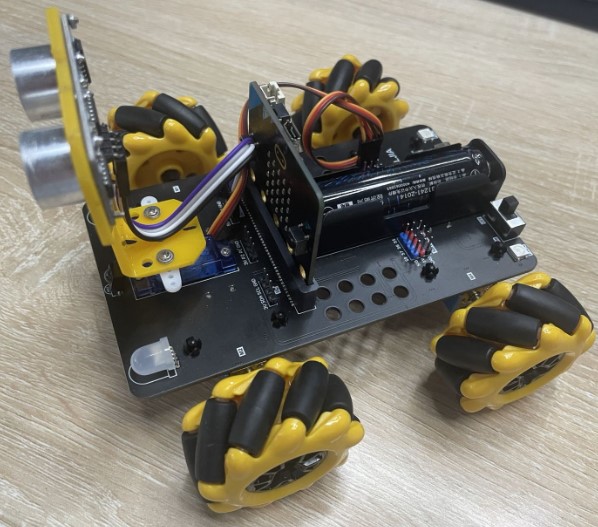
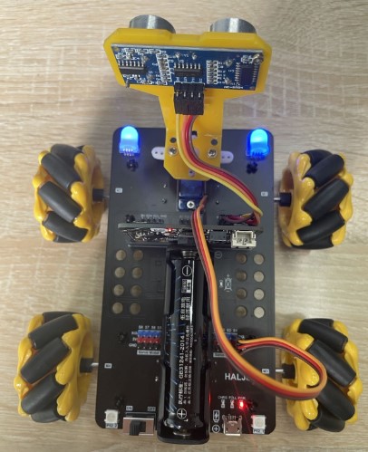
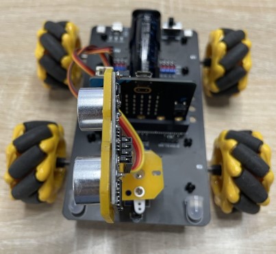
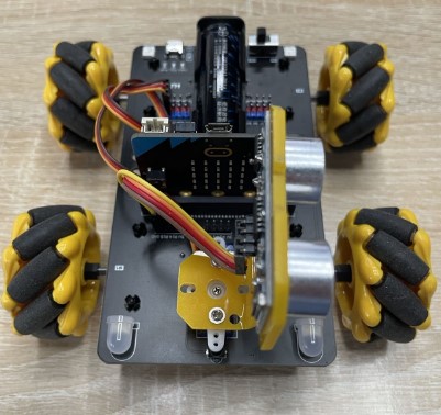
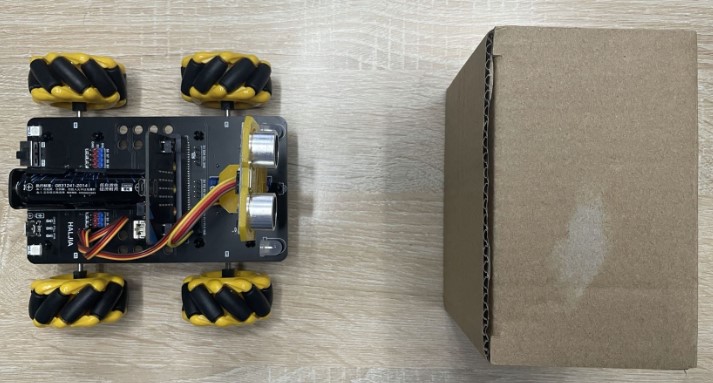
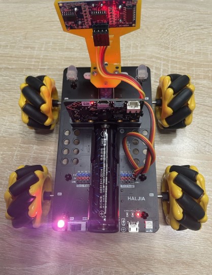
Install the micro:bit mainboard, ultrasonic module, wheels, servo and battery according to the picture above. The following is a step-by-step description of the installation of each accessory.
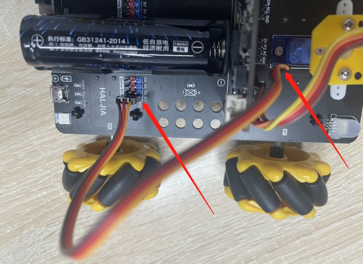
1.Installation of battery
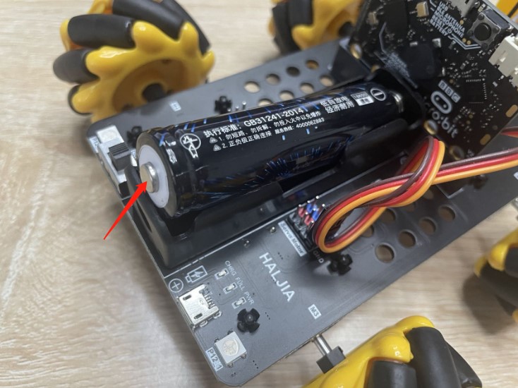
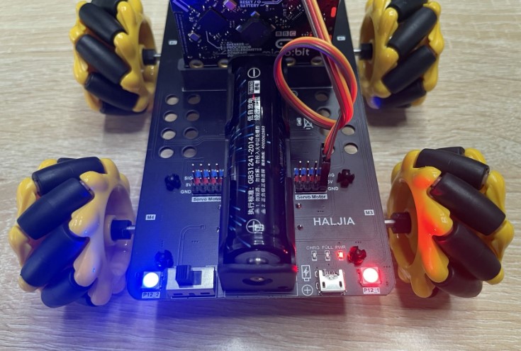
When installing the battery, the positive and negative directions should refer to the above picture, and the positive terminal pointed by the arrow is installed at the rear of the car. We should pay great attention not to reverse the battery. Otherwise, the battery can’t supply power or may cause other safety problems.
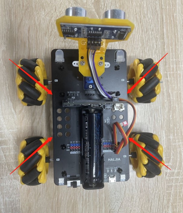
2.Installation of Mecanum wheel
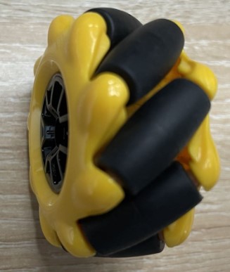
When installing the four Mecanum wheels, we should notice the orientation of the small wheels of each wheel as shown below. If you install the wrong wheel, it will cause abnormal travelling.
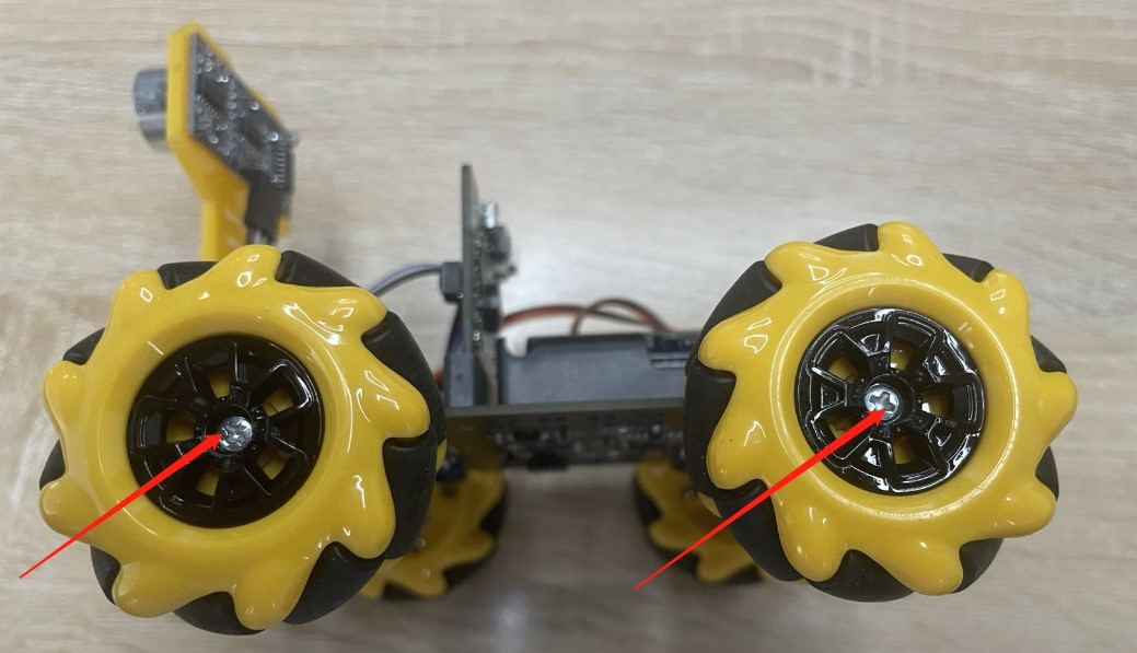
When wheels are in the right direction, tighten them with a screwdriver as shown below:
3.Installation of ultrasonic module
Install the ultrasonic module in the position shown below and then tighten the screw with a screwdriver.
Connection of the dupont cables in ultrasonic module:
Ultrasonic module VCC-->chassis 5V
Ultrasonic module GND-->chassis GND
Ultrasonic module Trig-->chassis P14
Ultrasonic module Echo-->chassis P15
Connect the dupont cables referring to the following picture:
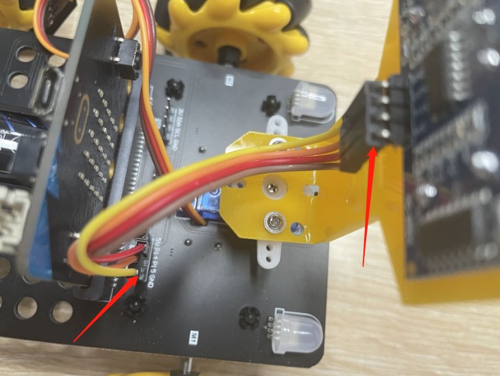
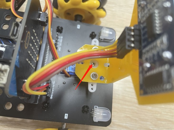
4.Installation of servo connection cables
Connect the servo with the dupont cables in the chassis of the car as shown below. Note that they are connected to the position of chassis S1, and that the cables’ color is in the order of brown, red and yellow, otherwise the servo will not work.
5.Installation of micro:bit mainboard
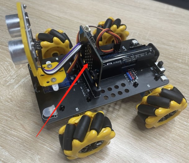
Note:The orientation of micro:bit mainboard should be the same with the picture above.
6.Installation of infrared remote control
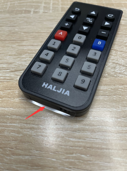

Take out the thin film the arrow points at to turn the remote control on. In the right picture, the remote control has been powered on and is in working condition.
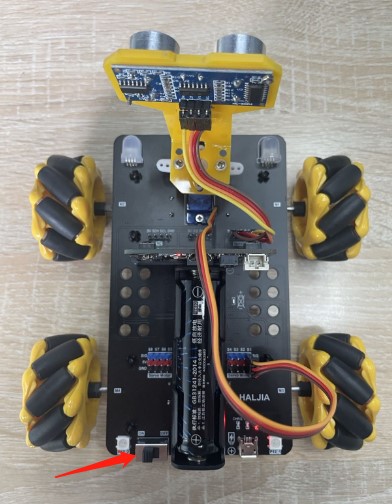
Start to test
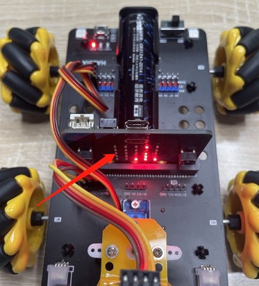
Pull the switch the arrow points at to ON, and the car has been turned on. Then, the power indicator light in the right rear of the car lights up and we can hear a piece of music sound. The car has been powered on successfully.
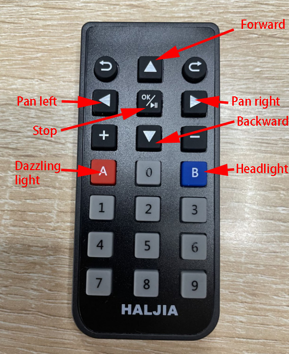
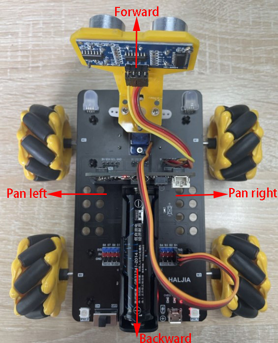
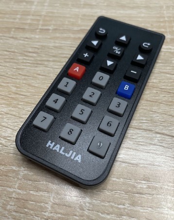
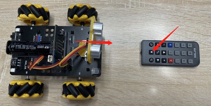
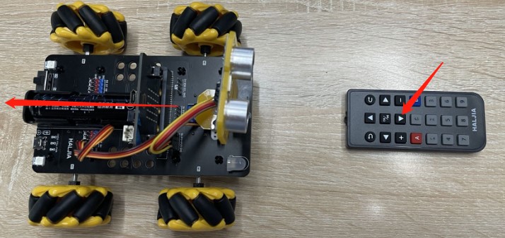
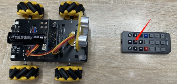
Press the button of remote control in the following picture to control the car forward, backward, pan left, pan right and stop. Note that the head of the remote control should be facing the car in order to increase the sensitivity of the remote control.
Note:We should take out the thin film in the infrared remote control to turn it on.
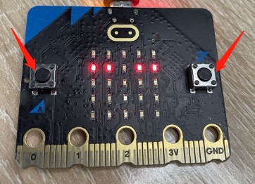
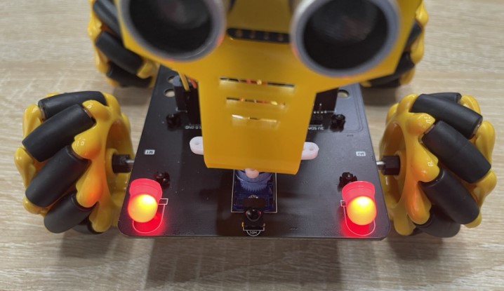
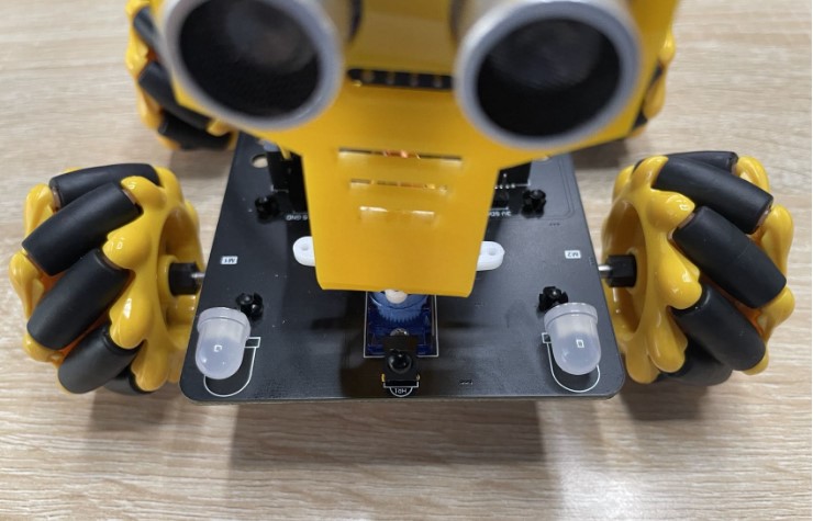
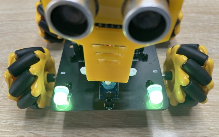
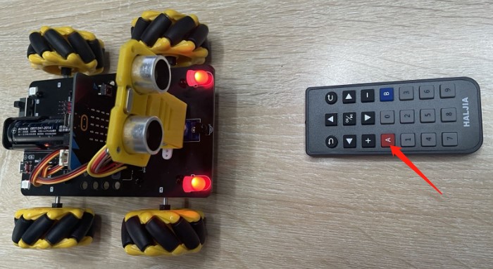
As shown below, press button A to light up the dazzling lights of the car:

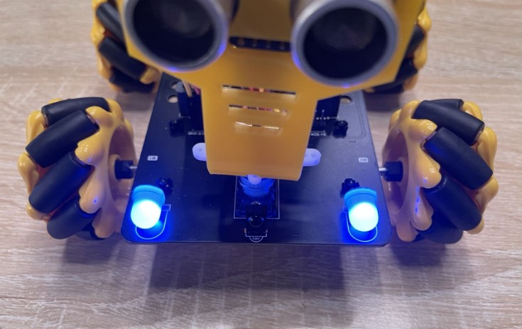
As shown below, press button B to light up the headlights of the car:
Introduction of Micro:bit
Brief introduction
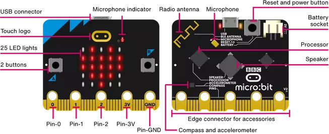
Micro:bit is a kind of pocket computer, which can make you have a better understanding of how the software and hardware can work synergistically. It is equipped with a LED light displayer, button, sensor, wireless, and many input and output functions. When programming, it can interact with you. You will learn hardware and software, which can bring you lots of fun in product development and programming. You can have a good knowledge of how the input, output and processor of the micro:bit is working, and the micro:bit can help you understand the working principle of the computer. When you are typewriting in the computer or touching screen on the phone, you are using an input device, which allows computer to perceive things that happen in the real word. Therefore, they can take actions according to above to make some things happen, which is usually in screen, sound and other output end.
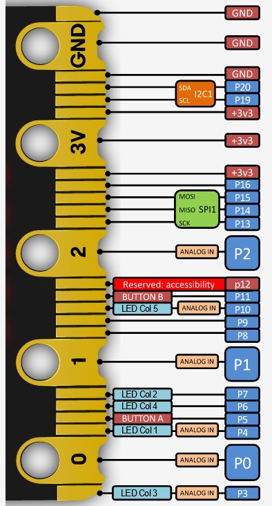
Introduction of Golden Finger Interface
What should you prepare?
A computer or tablet which can surf the Internet in order to load Microsoft MakeCode or Python coding editor. A USB cable is needed to link to your micro:bit mainboard.
Programming method
At present, we have two programming language: Makecode and Python. Makecode is equipped with graphic building block programming and Javascript programming. Makecode graphic building block programming is more suitable for beginners, while Javascript or Python programming is fit for someone who have some foundation.
Begin to learn
In the next chapter, we will learn how to build Makecode programming environment. And then the next chapter we will learn how to make the micro:bit work, program its functions and create your first project.
Build Makecode Programming Environment
We can choose on-line programming or off-line programming, both of which are available.
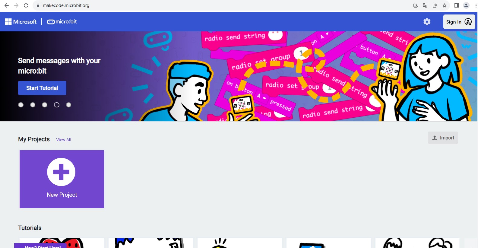
On-line programming
Enter the following website address directly, which is the most simple and fast method.
https://makecode.microbit.org/
Off-line programming(You can choose any of the following ways)
First: Execute the program “makecode-microbit-setup-win64.exe” to enter programming environment.
http://wiki2.haljia.com/download/microbit/smartrobot/makecode-microbit-setup-win64.exe

Second: Enter the following link to download the software of off-line programming.
https://makecode.microbit.org/offline-app
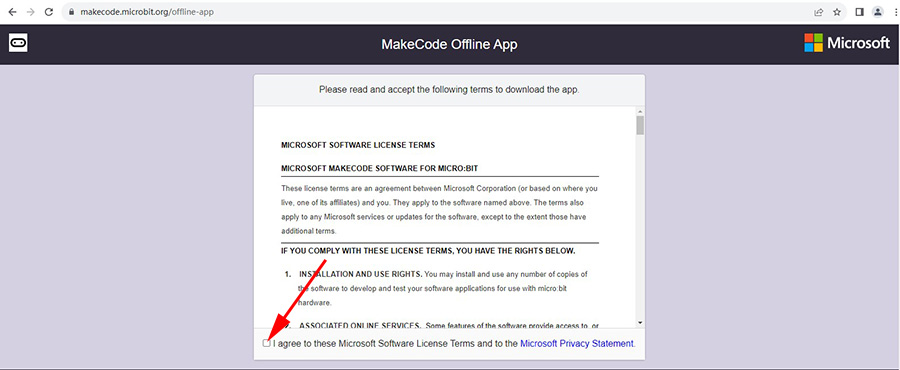
Click the position the arrow points at to enter the following page.
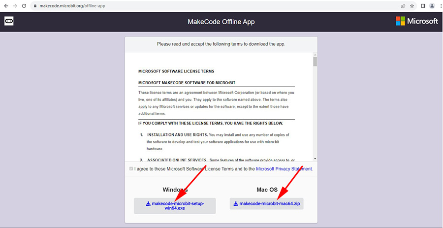
If you are Windows system, please click makecode-microbit-setup-win64.exe to download. If you are Mac OS system, please click makecode-microbit-mac64.zip to download. Having finished installation, please open MakeCode for micro:bit as shown below:

Third: Search MakeCode for micro:bit in Microsoft Store to download.
Create new project

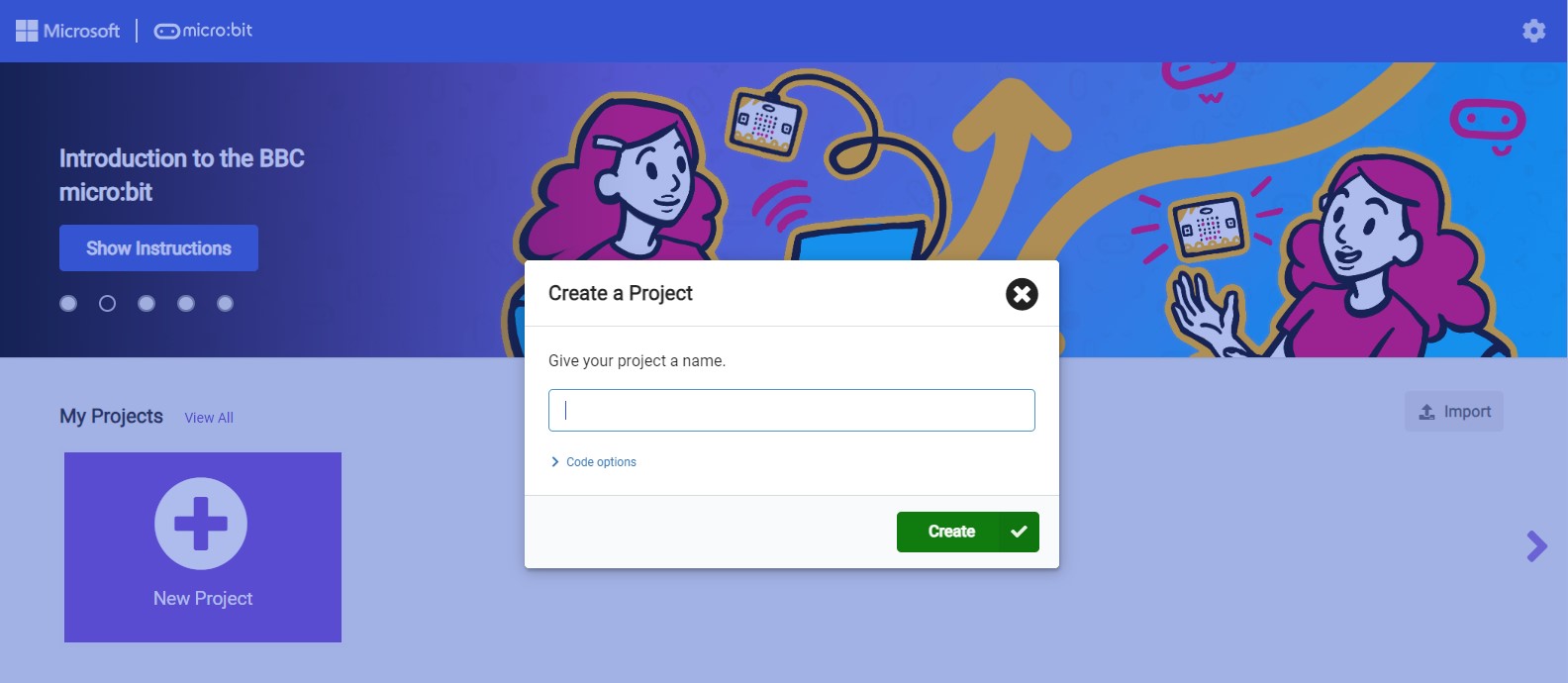
Click “New Project” and then start to program.
The First Project
Learning content
1.We should make the screen of micro:bit board display the number “1” through Makecode building block programming.
2.We should learn how to import finished project.
Start to program
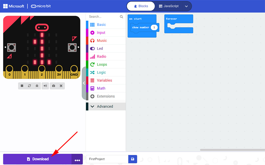
Open the Makecode and begin our first journey:

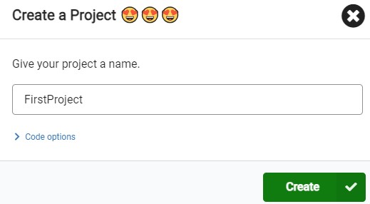
Click “New Project”, input the name of the project and then click “Create”.
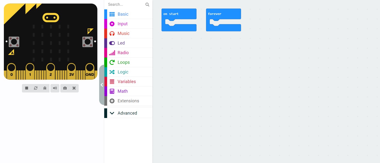
The middle function bar can implement many functions, and you can click them one by one to have a look.
There we click “Basic”:
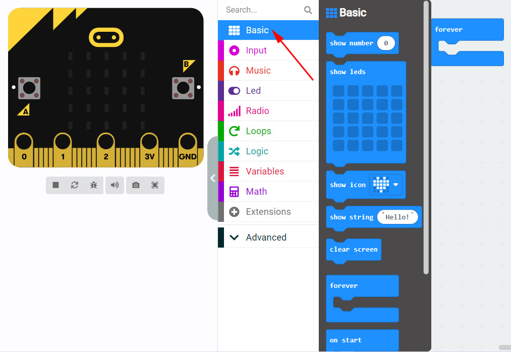
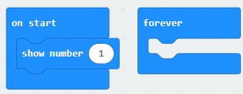
We should drag the show number “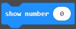 ” to “on start”.
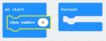
Alter the number “0” to “1”.
After having finished the project, click “Save” according to the following arrow:

We save it as "FirstProject.hex”.
http://wiki.haljia.com/download/microbit/smartrobot_mecanum/FirstProject.hex
Note:When we save files, we should add extension name: .hex. Otherwise, the file may not be used normally when we import it.
Then connect the micro:bit board with computer through USB cable.

Click “Download” to download the program to micro:bit.
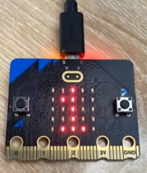
Start to test
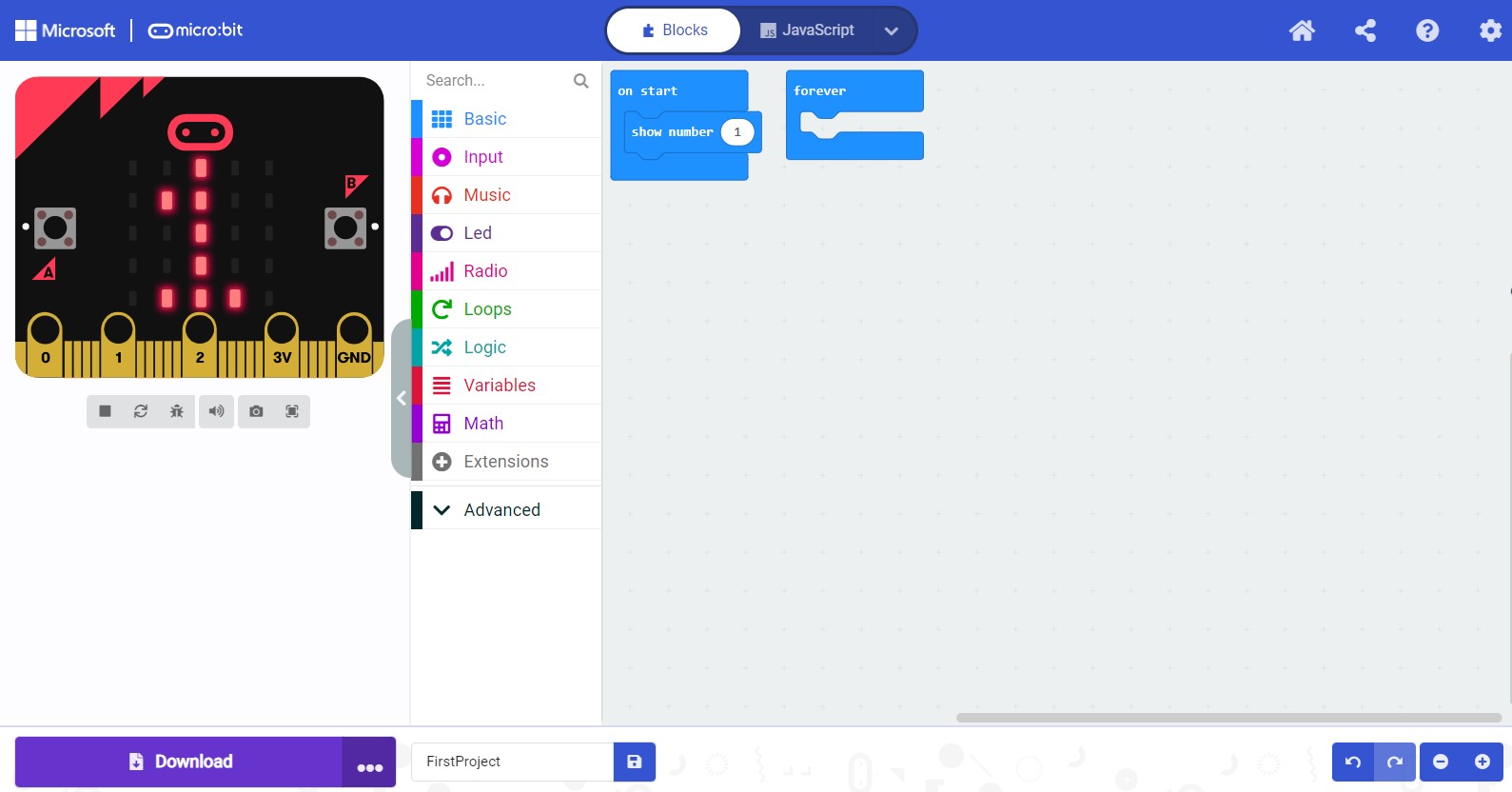
There will display number "1" in the LED screen when the micro:bit board is powered on. Then, we have finished our first project.
Import project
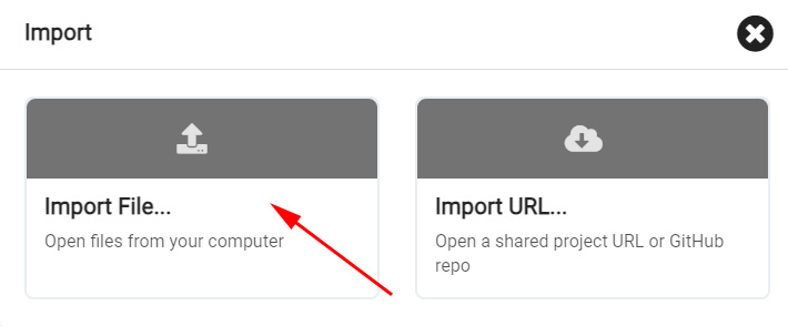
Load the program “FirstProject.hex” referring to the following operation order. Click “Import” first:
http://wiki.haljia.com/download/microbit/smartrobot_mecanum/FirstProject.hex
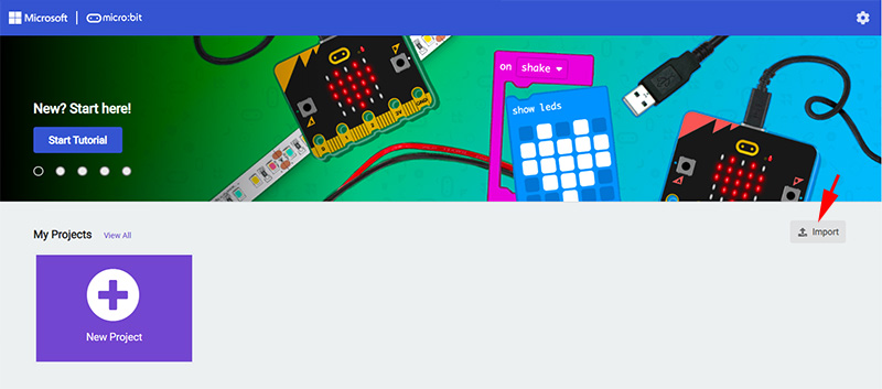
Import file:
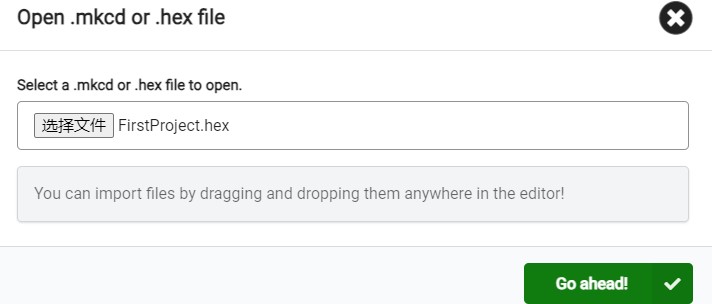
Choose file:
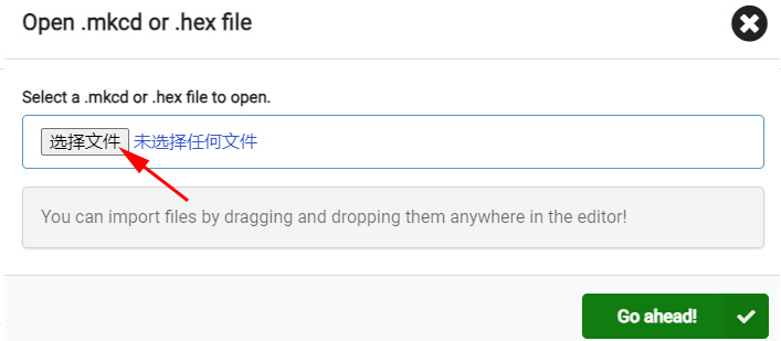
We should choose file with ".hex" extension name, or it can’t be opened.
Play Music
Learning content
1.We will implement music-playing by Makecode building block programming;
2.We will learn how to program the button of micro:bit;
3.We will learn the programming of music function.
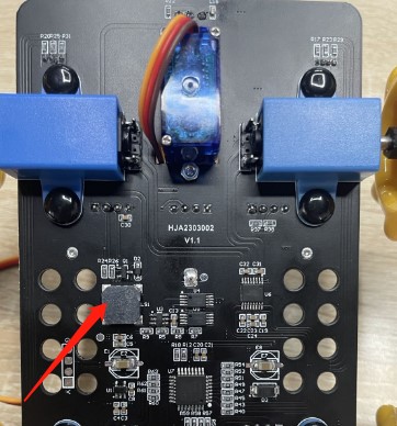
Buzzer music-playing
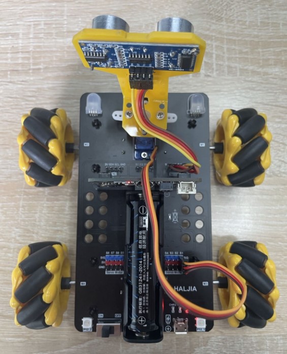
The bottom of the smart car is equipped with buzzer which can play music. The component the arrow points at is what called buzzer.
Start to program
Open Makecode and begin our programming:

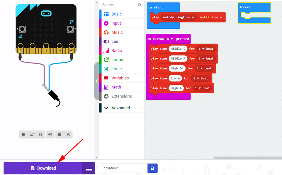
Create a new project named “PlayMusic”.
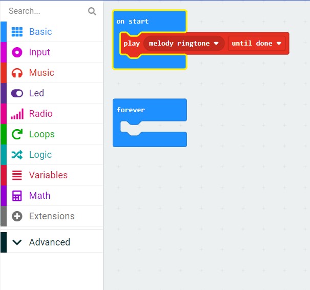
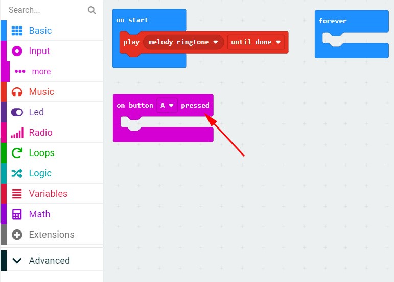
We can implement music function according to the page below:
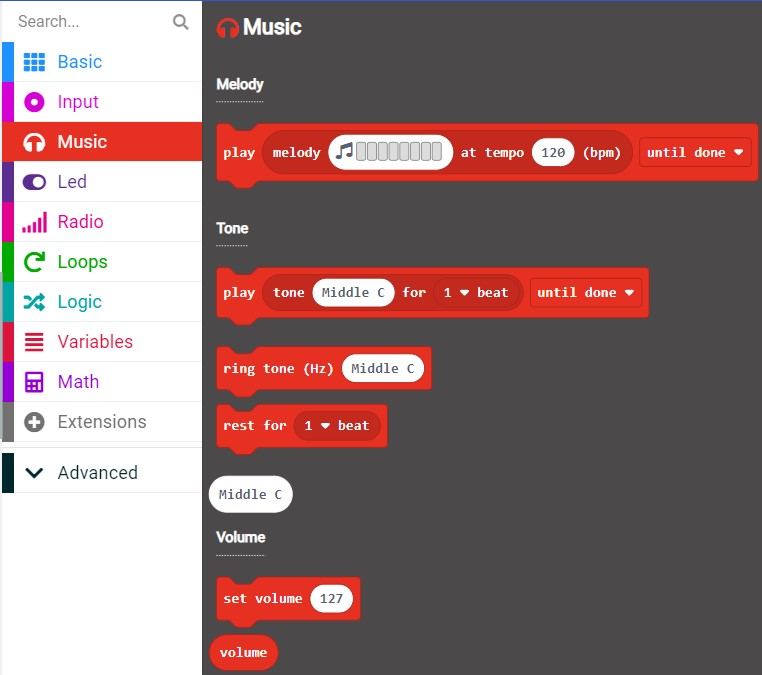
We choose to play the melody and the ringtone will be played when it’s powered on.
There are button A and button B in the micro:bit board. We can execute project by pressing the button.
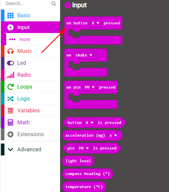
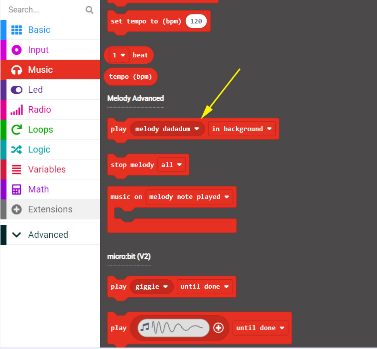
We can also play the song according to the music score and select the corresponding tone and beat. The yellow arrow in the picture below indicates the function of playing the tone:
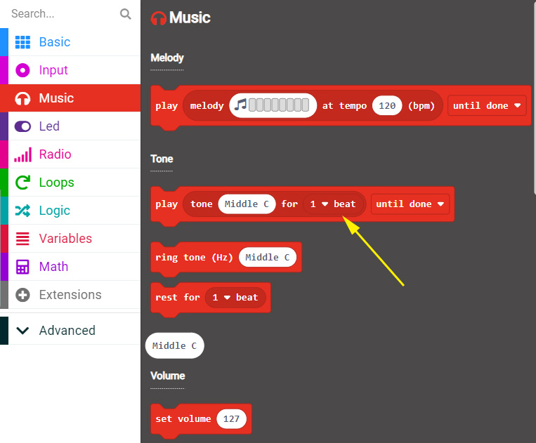
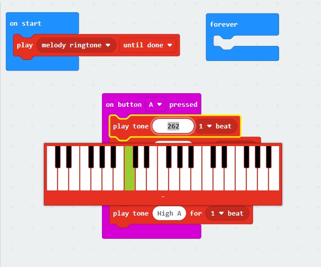
There we write a piece of music at will. You can play it by pressing the button A in the micro:bit board.
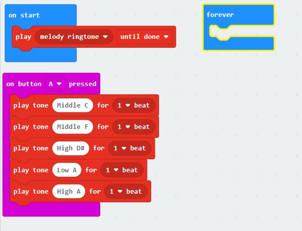
The written program “PlayMusic.hex” can be imported directly.
http://wiki.haljia.com/download/microbit/smartrobot_mecanum/PlayMusic.hex
Download the program to micro:bit.
Start to test
After the car is powered on, it will play a piece of music. When we press the button A, it will play the tone we have written.
Make Smart Car Move Forward
Learning content
1.We will learn the programming of how to make the car move forward through the rotation of motors M1, M2, M3 and M4.
2.Learn to use Funbit extension library to program the smart car.
Motion principle of smart car
The movement of the car can be implemented by the forward motion of motors M1, M2, M3 and M4, which can make the Mecanum wheels move forward.
Program the car to move step by step
We should open Makecode programming environment first.

Click “New Project”:
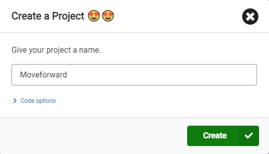
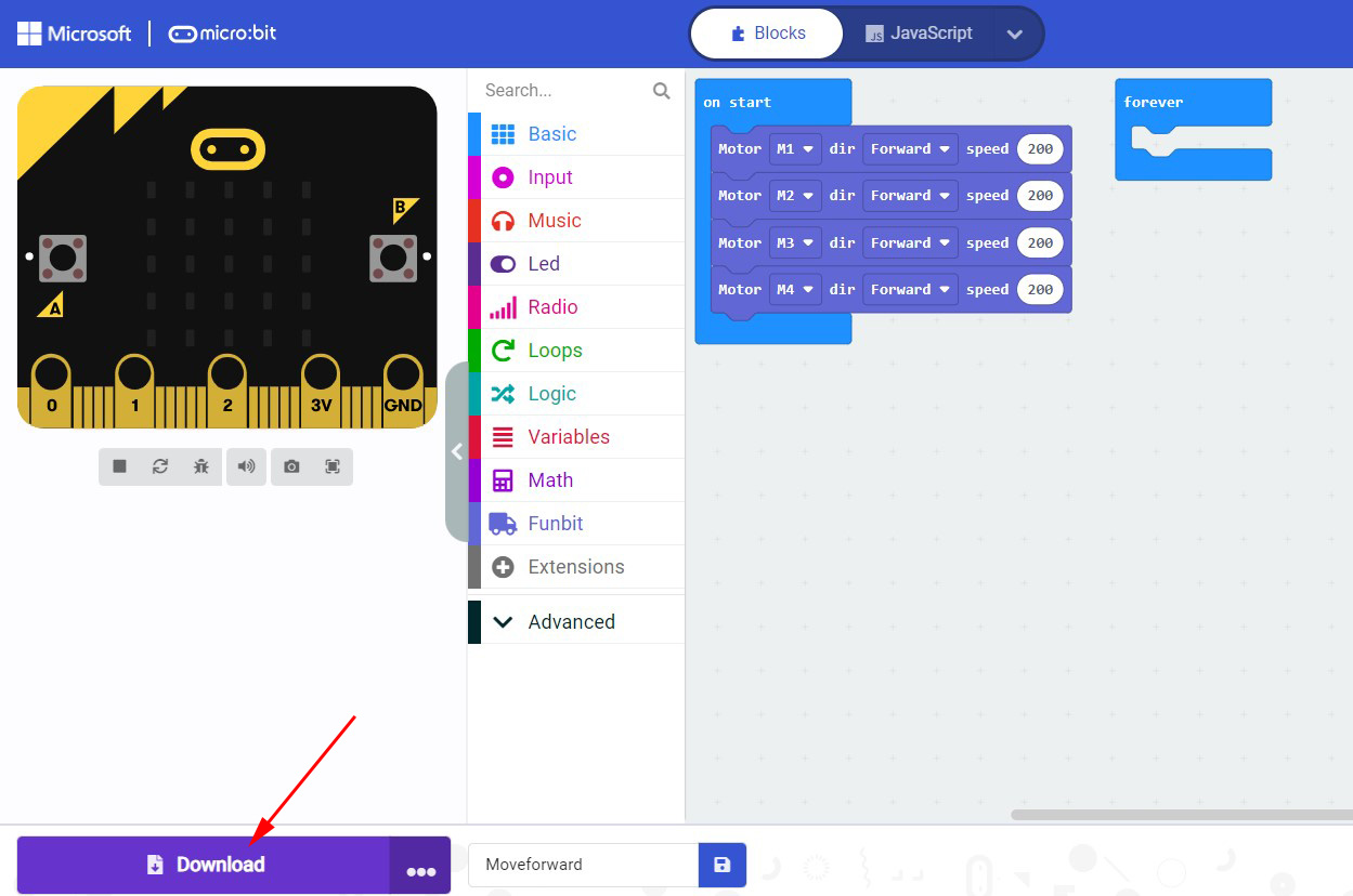
Input the name of the project “Moveforward”. You can also name it according to yourself. And then click “Create”.
Enter the following page:

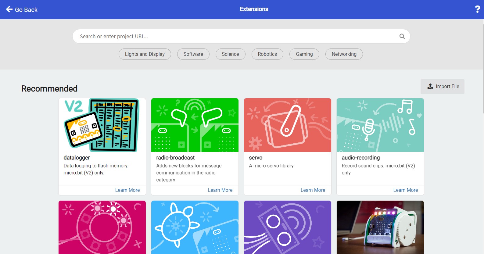
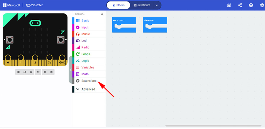
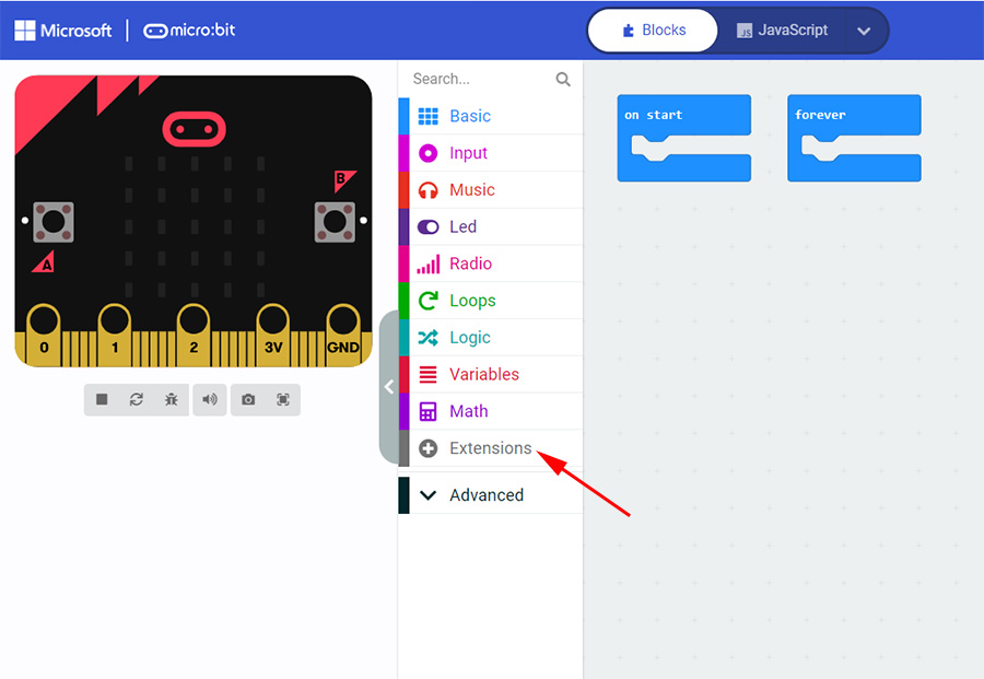
Click “Extensions” into the following page of adding extension library:

Here we input the following website address and press the button “Enter”:
https://github.com/szhengjiaanv/pxt-Funbit
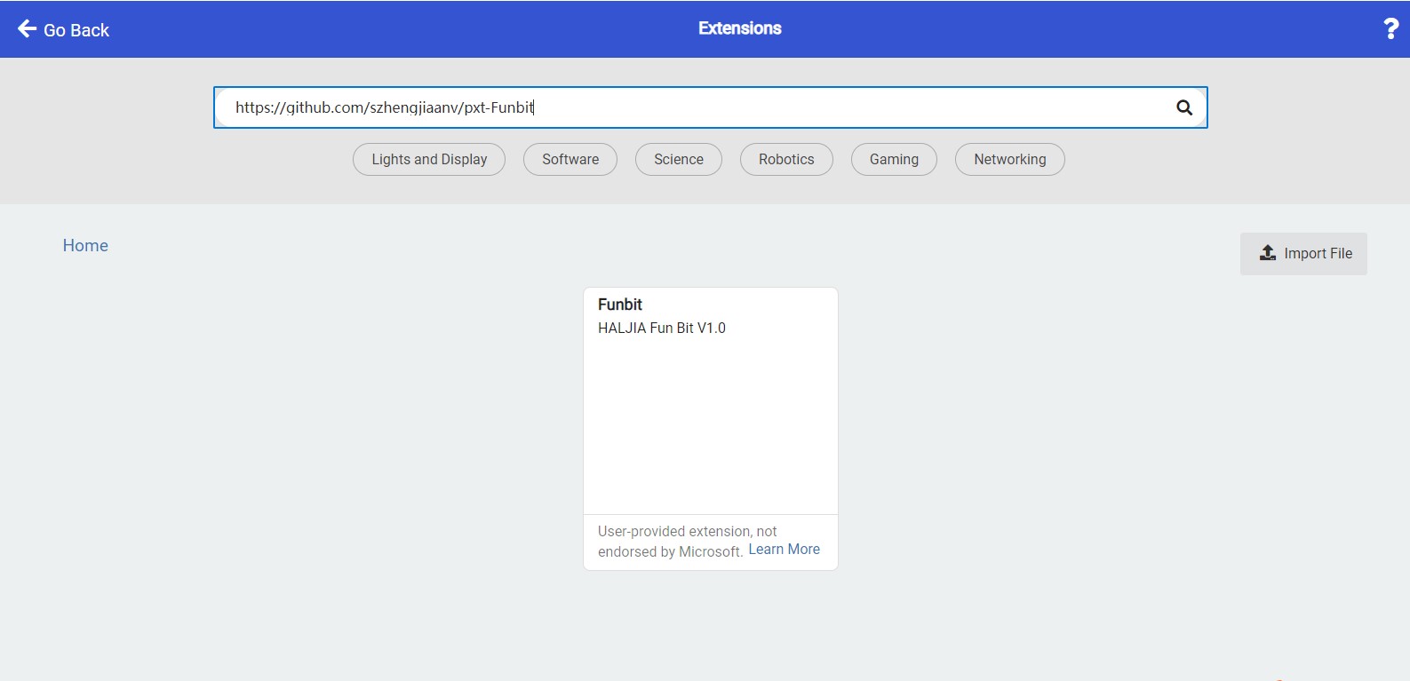
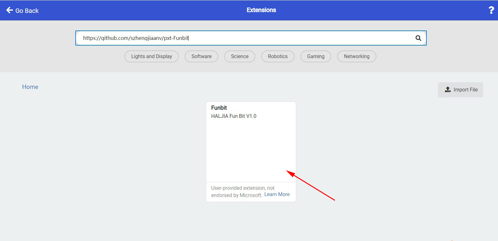
There will be a Funbit extension library in the page. Click the position the arrow points at and then the extension library is loaded.
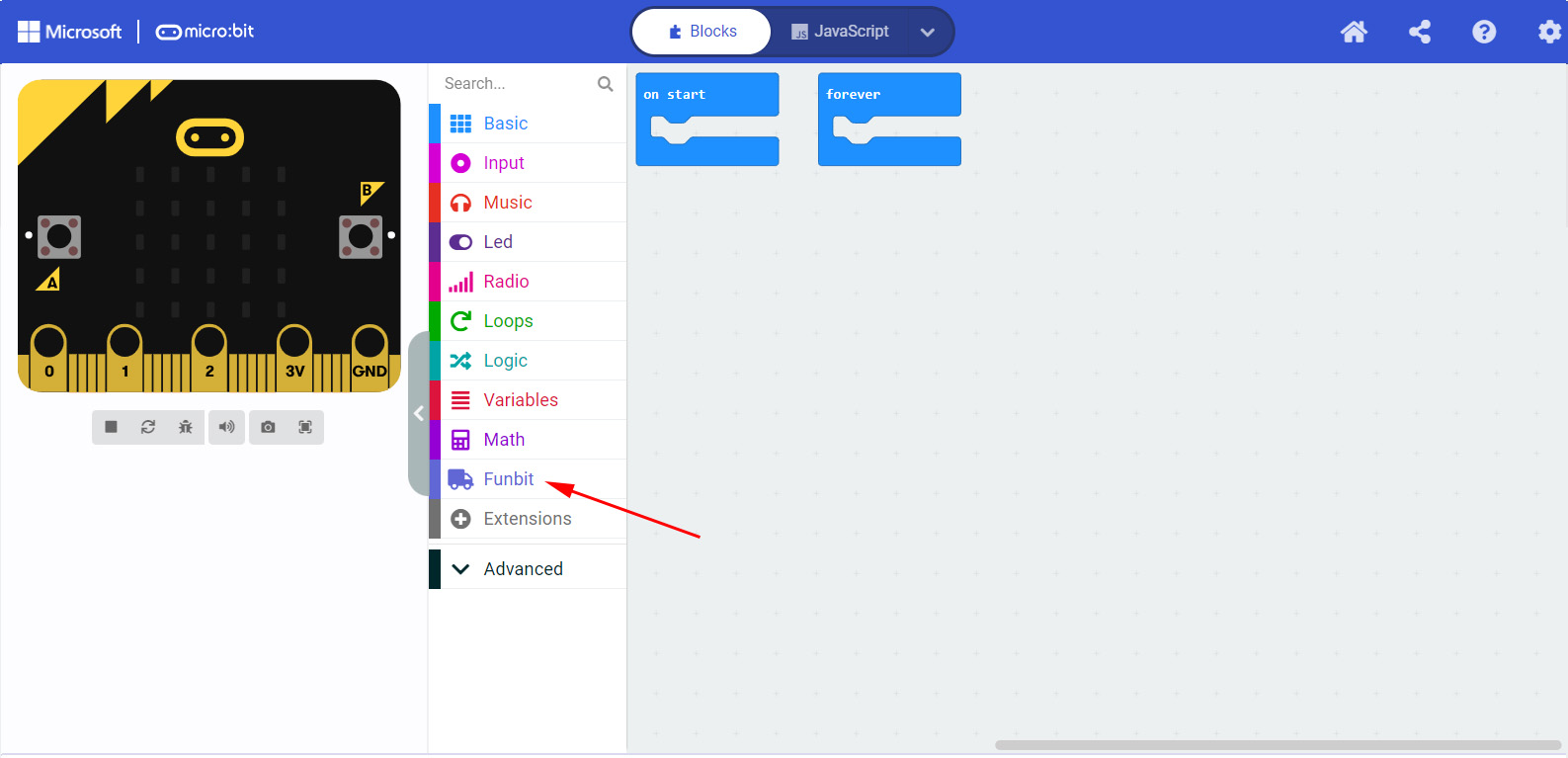
Click “Funbit” and it will show the following functions:
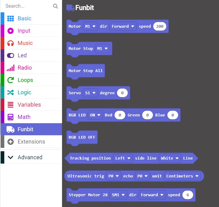
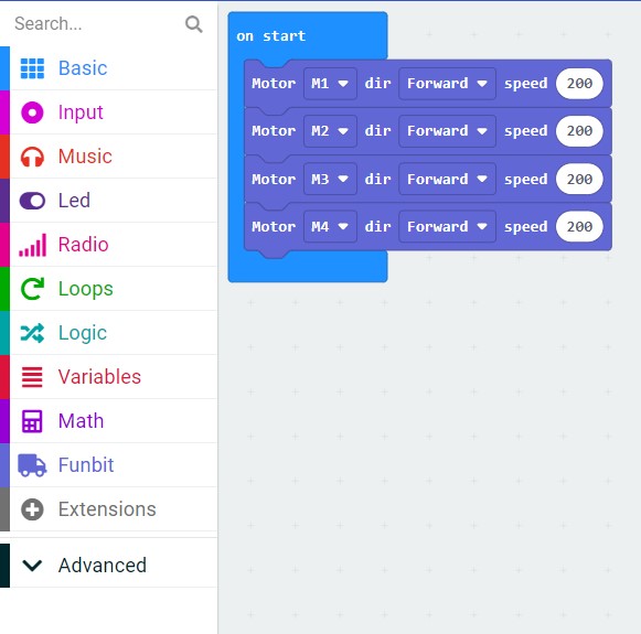
Click “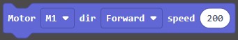 ” to add the function into the project, and drag it into “on start”.
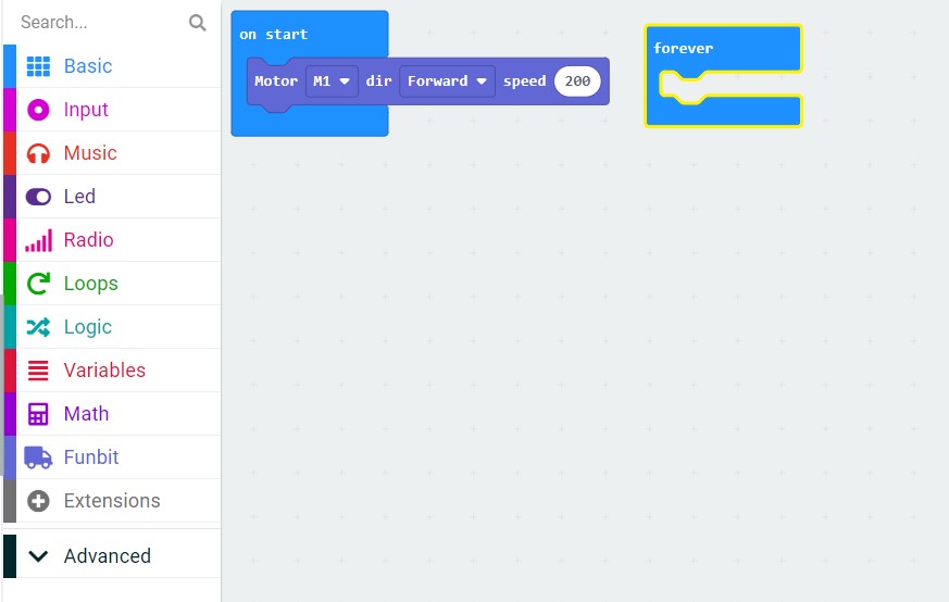
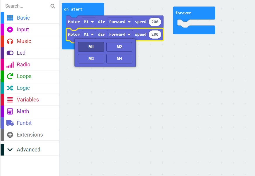
We can choose motor, direction (forward or backward), and the range of speed (0~255, default value: 200).
We can import the written program “Moveforward.hex” directly.
http://wiki.haljia.com/download/microbit/smartrobot_mecanum/Moveforward.hex
Then connect the micro:bit with computer and click “Download” to download the program to micro:bit board.
Start to test
After finishing download, insert micro:bit to the car and turn the car on. Then the car can move forward.
Turn on the Headlight of Smart Car
Learning content
1.Here we will implement the control of the opening, sparkling, and color of the car’s headlight by programming.
2.We can also learn to use the “pause” function of the “Basic” function Makecode contains.
Start to program
Open Makecode and begin our programming:

Create a new project “TurnOnHeadlight”:
Enter the following page:

Click “Extensions” and enter the following page of adding extension library:
Input the following website address and press the button “Enter”:
https://github.com/szhengjiaanv/pxt-Funbit
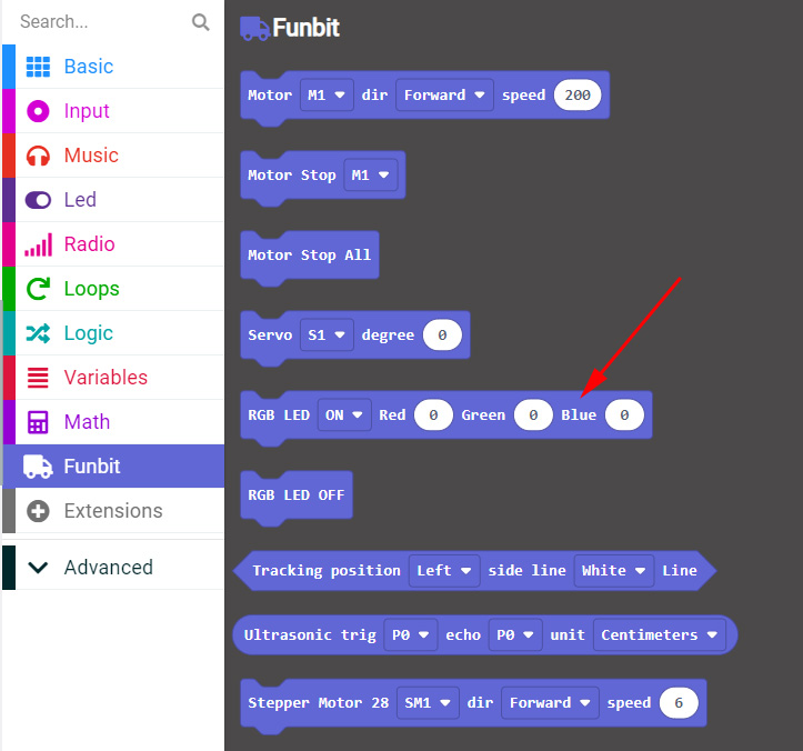
In the Funbit we choose “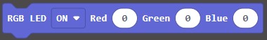 ” to control the opening and color of the RGB headlight.
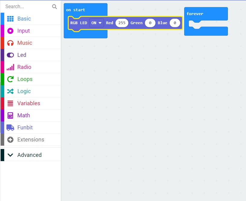
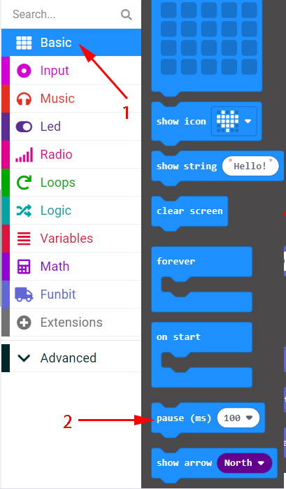
In the “Basic” function we choose “pause” function, which can set the time of pause.
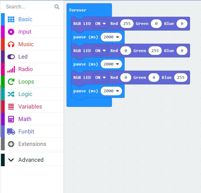
The following program is an example of controlling the color of the RGB light:
The written program “TurnOnHeadlight.hex” can be imported directly.
http://wiki.haljia.com/download/microbit/smartrobot_mecanum/TurnOnHeadlight.hex
Start to test
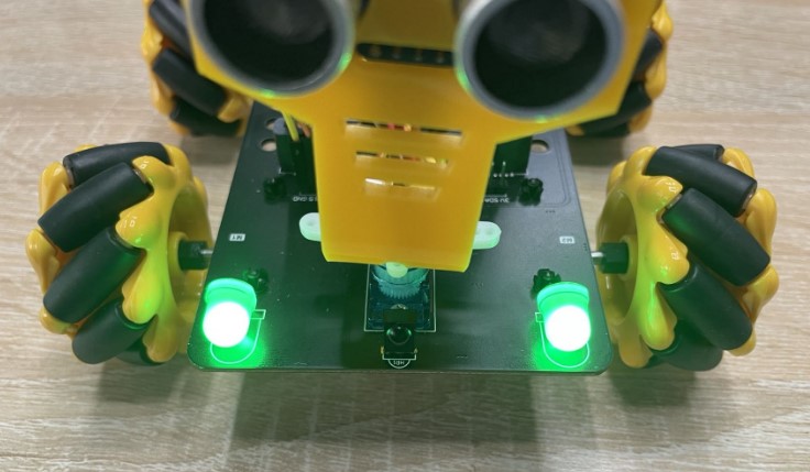
Download the program to micro:bit board. When the car is powered on, the RGB light will display red light with 2 seconds, green light with 2 seconds, and blue light with 2 seconds.
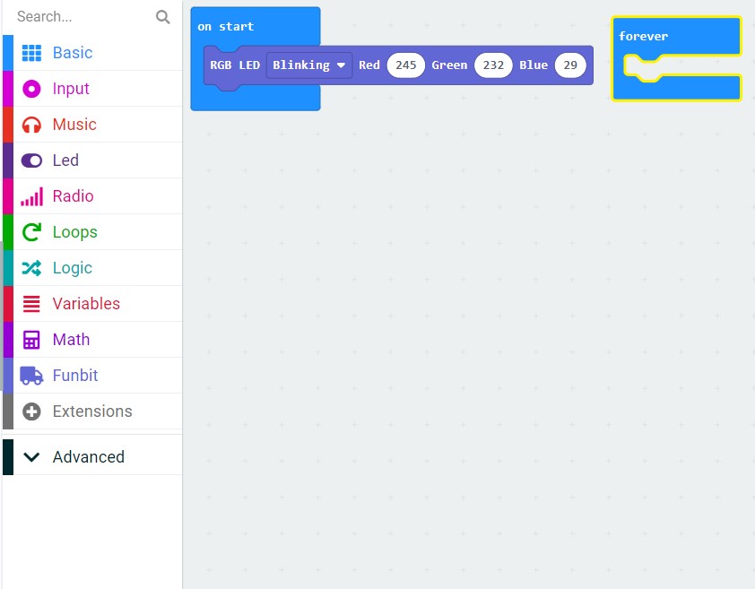
Flashing headlight of the car
Program according to the following picture. The RGB light mode should be set as "Blinking". The three basic colors (red, green, blue) of the RGB light should compose into yellow.
We can import the written program “FlashingHeadlight.hex” directly.
http://wiki.haljia.com/download/microbit/smartrobot_mecanum/FlashingHeadlight.hex
Start to test
Download the program to micro:bit board. When the car is powered on, it will sparkle yellow light.
Have Fun with Dazzling Light
Learning content
1.We will learn to implement the control of the opening and color of the dazzling light by programming;
2.We will learn to use the function of neopixel extension library of the dazzling light;
3.We will learn to program the button A and button B of the micro:bit board.
Start to program
Open Makecode and begin our programming.

Create a new project “RGBLight”.
And then enter the following page:
Click “Extensions”:
Adding Funbit extension library:
https://github.com/szhengjiaanv/pxt-Funbit
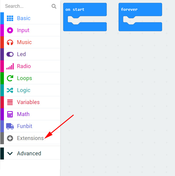
Click “Extensions” and input “neopixel” in the search bar. Click the neopixel library and enter:
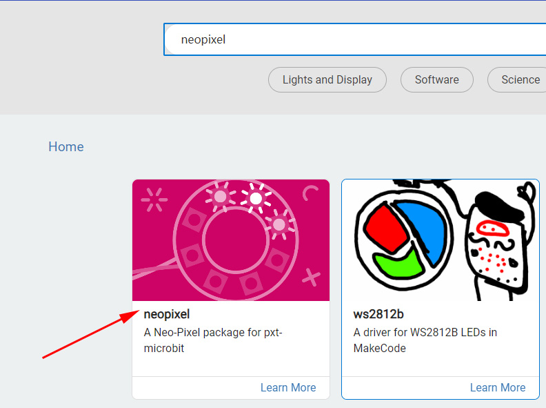
Then there will be a neopixel library in the page:
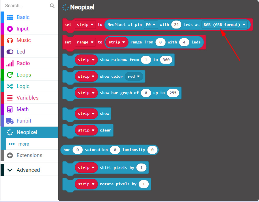
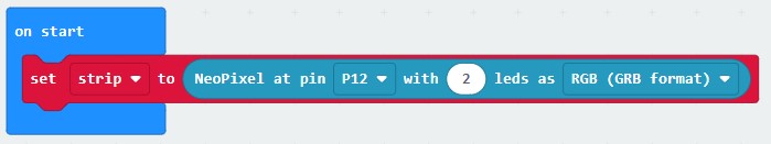
When the car is powered on, we set it up this way that the P12 port of the car should link 2 LED lights.
We will use the button A and button B of the micro:bit board.

Program as shown below:
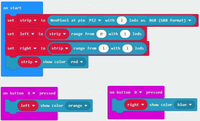
You can also import the written program “RGBLight.hex” directly.
http://wiki.haljia.com/download/microbit/smartrobot_mecanum/RGBLight.hex
Start to test
Download the program to micro:bit board.
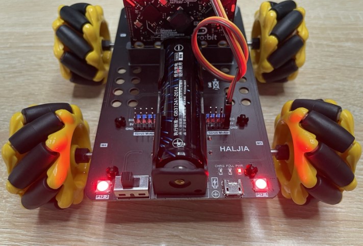
When the car is powered on, the two LED lights display red light.
Press the button A of the micro:bit board to make the left LED light display orange, and press button B to make the right LED light display blue.
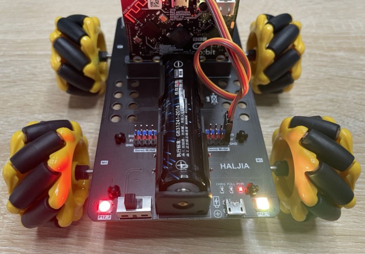
Press button A

Press button B
Infrared Remote Control
Learning content
We can learn the programming of infrared remote control. And use the remote control to control wirelessly the movement direction of the car: forward, backward, pause, turn on the headlight, etc.
Introduction of the infrared remote control
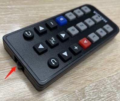
The arrow in the left figure points to the IR receiver head, which is responsible for receiving commands, and the arrow in the right figure points to the IR transmitter head, which is responsible for transmitting commands to the car. After the car’s infrared receiver head receives the command, it starts to execute the command.

Take out the thin film to power on the remote control. The right picture shows the working condition of the controller.
The infrared remote control should be used in room to avoid the interference of sunlight.
Start to program
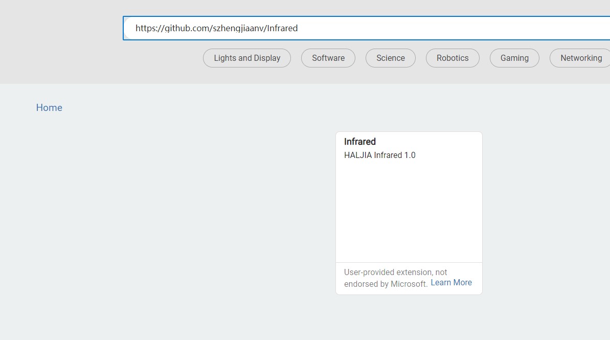
Create a new project “IRControl” and load the extension library.

We need to load the extension library of the remote control:
https://github.com/szhengjiaanv/Infrared
and Funbit extension library of the car:
https://github.com/szhengjiaanv/pxt-Funbit
After finishing loading:
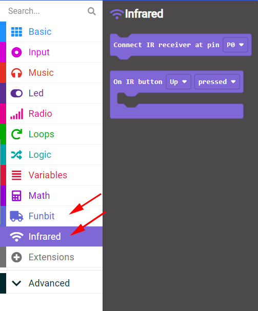
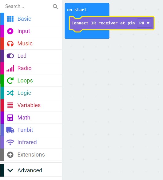
When we turn on the car, the infrared receiver module will be opened, and then link it to P8.
Add the button UP of the infrared remote control to deal with functions.
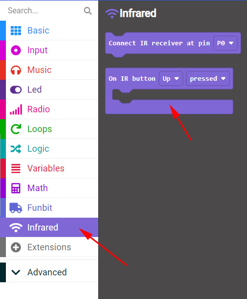
When we press the button UP, motors M1, M2, M3 and M4 rotate forward and the car moves forward.
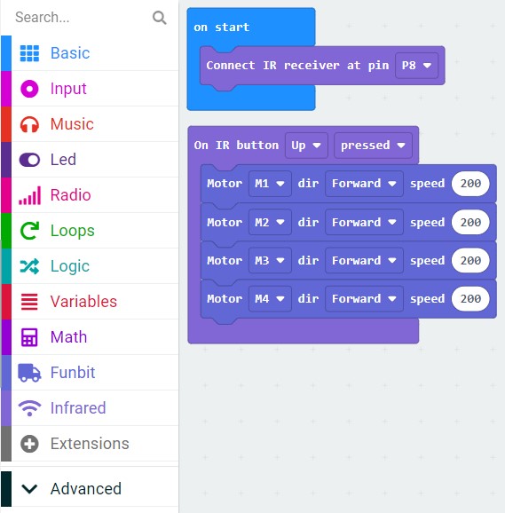
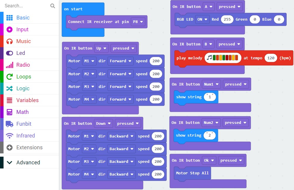
We program it as shown below:
We can also import the written program “IRControl.hex” directly.
http://wiki.haljia.com/download/microbit/smartrobot_mecanum/IRControl.hex
Start to test
Download the program to the micro:bit board, then install it to the car and turn on the car.
When we press the button UP, the car will move forward:
When we press the button Down, the car will back off:
When we press the button OK, the car will pause:
When we press the button A, the headlights of the car will display red light.
When we press the button B, the car will play music.
Press the number 1 and then the Micro:bit board will display “1”. Press number 2 and then the board will display “2”.
Control of the Joystick
Learning content
1.Learn to program the joystick to control the smart car.
2.Learn the programming of the two micro:bit boards’ wireless communication. The joystick is equipped with a micro:bit board and the car is also equipped with a micro:bit board.
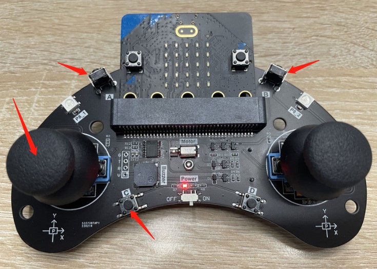
Joystick
We can use the following joystick to control the car. And we need to buy the controller first as shown below:
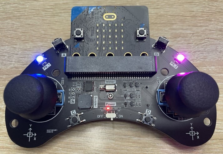
Our joystick is equipped with power switch, two joysticks, four buttons(A B C D), two colorful LED lights. We can control the car to forward and backward by buttons or joysticks.
The joystick connects with the car wirelessly.
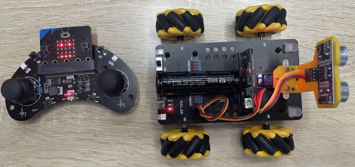
We need to prepare two micro:bit boards first. And both the joystick and the car should be equipped with a micro:bit board. Through wireless connection, the micro:bit of joystick can communicate with the micro:bit of the car, receive and send commands to implement the joystick’s motion control to the car.
Program the joystick
Create a new project “Joystick” and load the extension library:
https://github.com/szhengjiaanv/Joybit
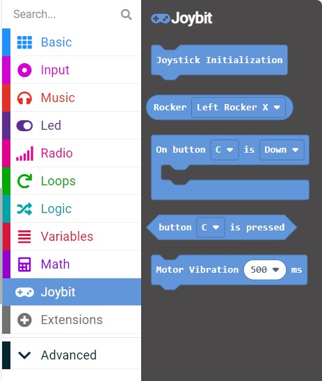
There is also the function of “Radio” as shown below:
Start our programming:
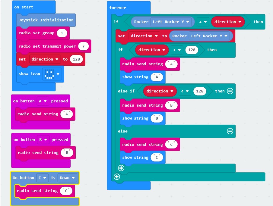
We can also import the written program “Joystick.hex” directly.
http://wiki.haljia.com/download/microbit/smartrobot_mecanum/Joystick.hex
Download the program to micro:bit board.
Program the car
Create a new project “WirelessCar” and load the extension library:
https://github.com/szhengjiaanv/pxt-Funbit

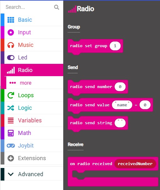
There is also the function of “Radio” as shown below:

Start our programming:
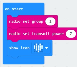
We should set radio set group and transmit power when the car is powered on.
The radio set group of the car should be the same with the joystick. If the car’s radio set group is 1, then the joystick’s should be 1. Otherwise, it can’t connect wirelessly and can’t control the car.
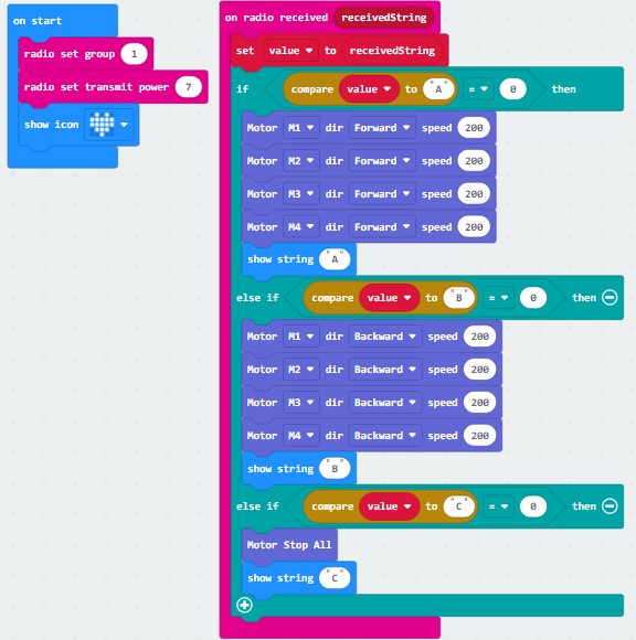
When the car receives the order “A”, it will move forward. When receiving the order “B”, it will back off. When receiving the order “C”, it will pause.
We can import the written program “WirelessCar.hex” directly.
http://wiki.haljia.com/download/microbit/smartrobot_mecanum/WirelessCar.hex
Download the program to micro:bit board.
Start to test
Turn on the joystick and the car. If we push the left joystick forward, the car will move forward. If we pull the joystick backward, the car will back off. If the joystick returns to the middle, the car will pause.
Or press button A to forward, press button B to backward, and press button C to pause.

Motion Control of the Servo
Learning content
Learn to control the rotation and angle of the servo.
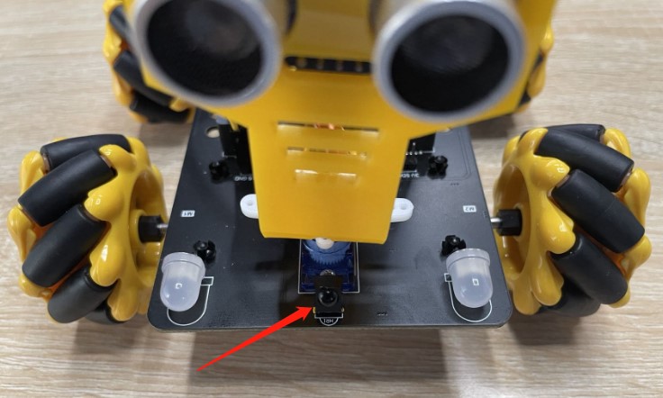
Introduction of the servo
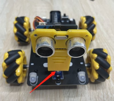
The arrow points to the servo, which can change the direction of ultrasonic ranging after its rotation.

Servo interface has 8 ports from S1 to S8, and the servo cable is connected to the position of chassis S1. The wires’ color is in the order of brown, red and yellow, otherwise the servo will not work.
Start to program
Create a new project “ServoMotion” and load the Funbit extension library.
https://github.com/szhengjiaanv/pxt-Funbit
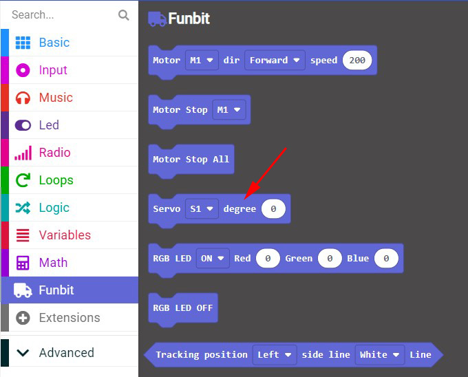
In the Funbit library we use the servo’s rotation function.
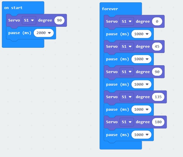
Turn on the car to turn the servo to 90 degrees.
After 2 seconds, the servo rotates circularly at 0 degree, 45 degrees, 90 degrees, 135 degrees, and 180 degrees.
The written program “ServoMotion.hex” can be imported directly.
http://wiki.haljia.com/download/microbit/smartrobot_mecanum/ServoMotion.hex
Click “Download” to download the program to micro:bit.
Start to test
When the car is powered on, the servo will turn to 90 degrees.
After 2 seconds, the servo rotates circularly at 0 degree, 45 degrees, 90 degrees, 135 degrees, and 180 degrees.
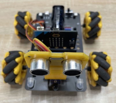
90 degrees 0 degree
180 degrees
Following Motion of Smart Car
Learning content
1.Learn about the following principle of the car and the use of ultrasonic ranging module;
2.Learn to create and call functions;
3.Learn the programming of the car’s following motion of ultrasonic ranging module.
Basic introduction of following motion

The arrow points to the ultrasonic ranging module, which can judge the distance to the object in front of the car.
By judging the distance, if the car is close to object, it will back off, or it will move ahead.
The trig port of ultrasonic ranging module links to the P14 port of the micro:bit board. And the echo port links to the P15 port of the micro:bit board.
Start to program
Create a new project “FollowingObject”:
We need to load the Funbit extension library of the car:
https://github.com/szhengjiaanv/pxt-Funbit

The trig port of ultrasonic ranging module links to the P14 port of the Micro:bit board. And the echo port links to the P15 port of the Micro:bit board.
With the two ports, we can know the distance to object when programming. If the distance is over 12cm, the car will move forward; if it’s less than 12cm, the car will back off and then move following the object all the time.
Here we will use function:
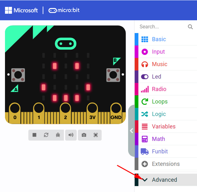
Click “Advanced” and then appear the following page:
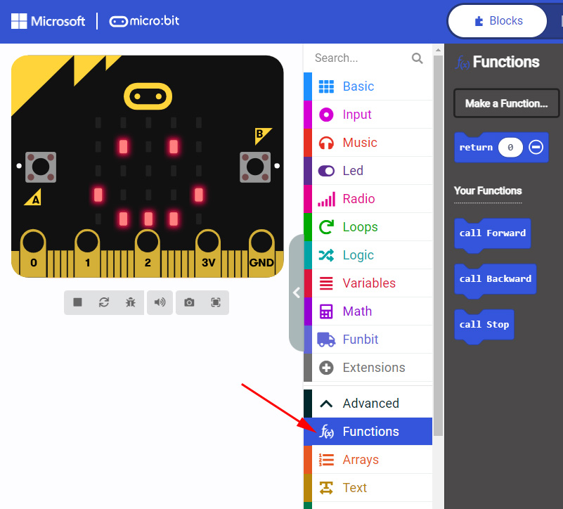
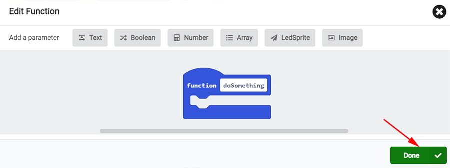
We can create functions in “Functions”, and then call these functions. We should create functions of “Forward”, “Backward” and “Stop”.
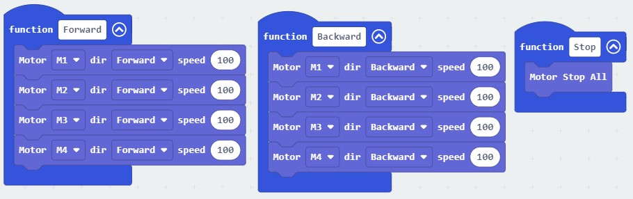
In “forever”, we call functions of “Forward”, “Backward” and “Stop” to implement following motion.

We can also import the written program “FollowingObject.hex” directly.
http://wiki.haljia.com/download/microbit/smartrobot_mecanum/FollowingObject.hex
Start to test
Download the program to micro:bit board and turn on the car.
The car will move forward following the object all the time. When it’s close to the object, it will draw back.
Panning Motion of Smart Car
Learning content
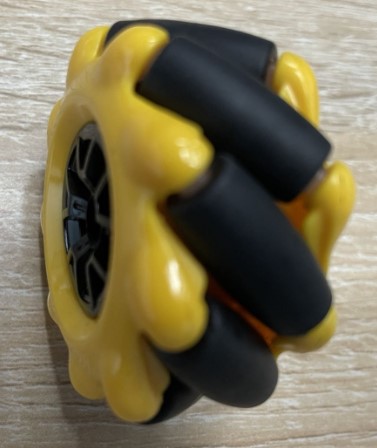
1.Learn about Mecanum wheels;
2.Learn to make the car pan left and pan right.
Basic introduction of Mecanum wheels
Mecanum Wheel: Mecanum for short, consisting of hubs and rollers that surround the hubs.
Roller: A small driven roller without power.
The angle between the axis of the roller and the axis of the hub is 45 degrees.
There are two types of wheels, wheel A (left-handed) and wheel B (right-handed), which are mirror relationship of each other, so we should pay attention to the direction when installing them.

Wheel A Wheel B
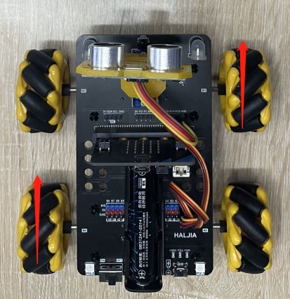
Pan left
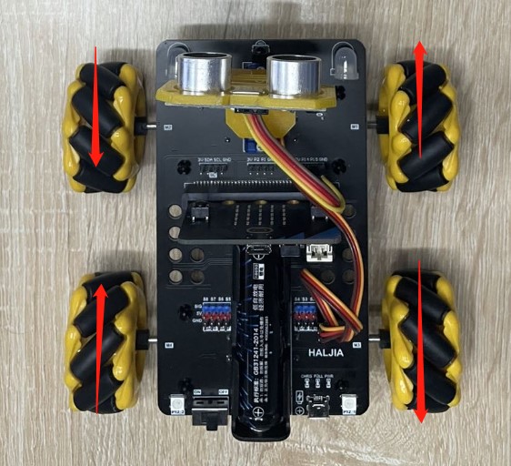
The installation direction of Mecanum wheels refers to the above picture. To implement the left panning, each wheel should move according to the arrow direction of the above picture: M1 and M4 move forward, M2 and M3 move backward.
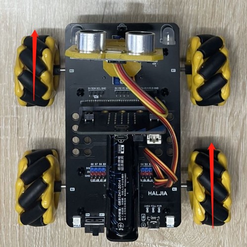
Pan right
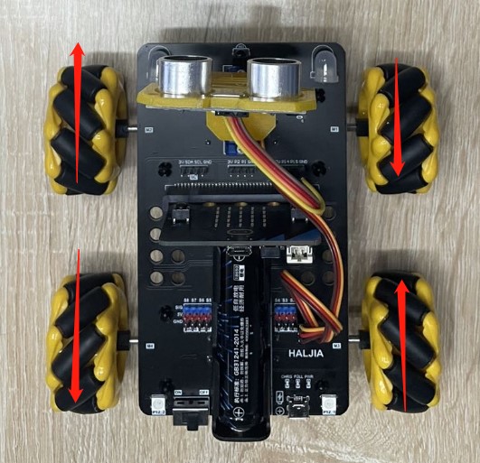
To implement the right panning, each wheel should move according to the arrow direction of the above picture: M1 and M4 move backward, M2 and M3 move forward.
Start to program
Create a new project “ParallelMotion”:
We need to load the Funbit extension library of the car:
https://github.com/szhengjiaanv/pxt-Funbit
Here we will use function:
Click “Advanced” and then appear the following page:

We can create functions in “Functions”, and then call these functions. We should create functions of “Forward”, “Backward”, “ParallelLeft” and “ParallelRight”.
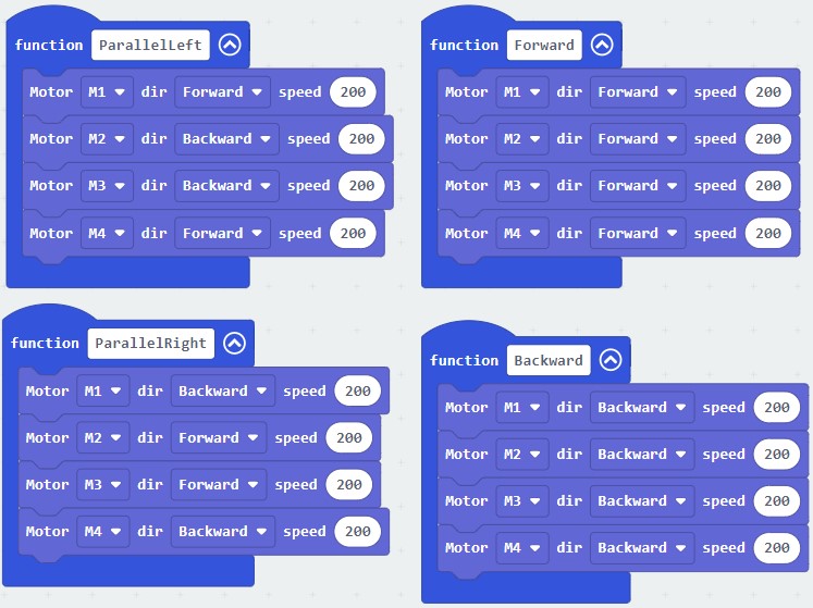
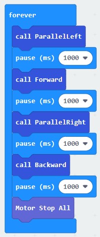
In “forever”, we call functions of “Forward”, “Backward”, “ParallelLeft” and “ParallelRight”.
We can also import the written program “ParallelMotion.hex” directly.
http://wiki.haljia.com/download/microbit/smartrobot_mecanum/ParallelMotion.hex
Start to test
Download the program to micro:bit board and then turn on the car.
The smart car moves following the direction of “ParallelLeft”, “Forward”, “ParallelRight” and “Backward” to form a square.
Tilt Motion of Smart Car
Learning content
1.Learn about Mecanum wheels;
2.Learn to make the car tilt 45 degrees to the left and right to move forward and move backward.
Basic introduction of Mecanum wheels
Mecanum Wheel: Mecanum for short, consisting of hubs and rollers that surround the hubs.
Roller: A small driven roller without power.
The angle between the axis of the roller and the axis of the hub is 45 degrees.
There are two types of wheels, wheel A (left-handed) and wheel B (right-handed), which are mirror relationship of each other, so we should pay attention to the direction when installing them.


Wheel A Wheel B
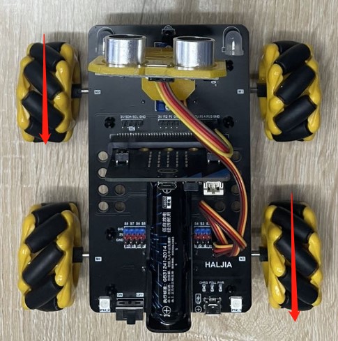
Tilt 45 degrees to the left to move forward
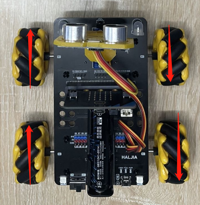
The installation direction of Mecanum wheels refers to the above picture.
To make the car tilt 45 degrees to the left to move forward, each wheel should move according to the arrow direction of the above picture: M1 and M4 move forward, M2 and M3 stop motion.
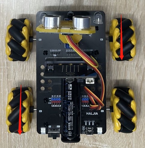
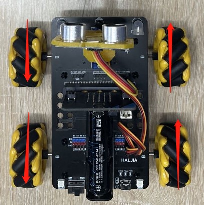
Tilt 45 degrees to the right to move forward
To make the car tilt 45 degrees to the right to move forward, each wheel should move according to the arrow direction of the above picture: M1 and M4 stop motion, M2 and M3 move forward.
Tilt 45 degrees to the left to move backward
To make the car tilt 45 degrees to the left to move backward, each wheel should move according to the arrow direction of the above picture: M1 and M4 stop motion, M2 and M3 move backward.
Tilt 45 degrees to the right to move backward
To make the car tilt 45 degrees to the right to move backward, each wheel should move according to the arrow direction of the above picture: M1 and M4 move backward, M2 and M3 stop motion.
Start to program
Create a new project “TiltMotion”:
We need to load the Funbit extension library:
https://github.com/szhengjiaanv/pxt-Funbit
Here we will use function:
Click “Advanced” and then appear the following page:
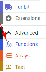
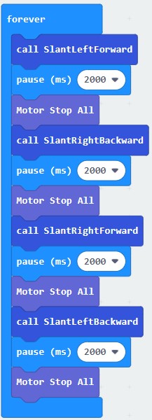
We can create functions in “Functions”, and then call these functions. We should create functions of “SlantLeftForward”, “SlantRightForward”, “SlantLeftBackward” and “SlantRightBackward”.
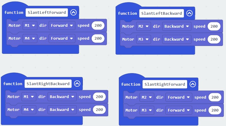
In “forever”, we call functions of “SlantLeftForward”, “SlantRightForward”, “SlantLeftBackward” and “SlantRightBackward”.
We can also import the written program “TiltMotion.hex” directly.
http://wiki.haljia.com/download/microbit/smartrobot_mecanum/TiltMotion.hex
Start to test
Download the program to micro:bit board and then turn on the car.
The smart car moves following the direction of “SlantLeftForward”, “SlantRightBackward”, “SlantRightForward” and “SlantLeftBackward” to form a shape of “V”.
Rotary Motion of Smart Car
Learning content
1.Learn about Mecanum wheels;
2.Learn to make the car rotate clockwise and rotate counterclockwise.
Basic introduction of Mecanum wheels
Mecanum Wheel: Mecanum for short, consisting of hubs and rollers that surround the hubs.
Roller: A small driven roller without power.
The angle between the axis of the roller and the axis of the hub is 45 degrees.
There are two types of wheels, wheel A (left-handed) and wheel B (right-handed), which are mirror relationship of each other, so we should pay attention to the direction when installing them.

Wheel A Wheel B
Rotate clockwise
The installation direction of Mecanum wheels refers to the above picture.
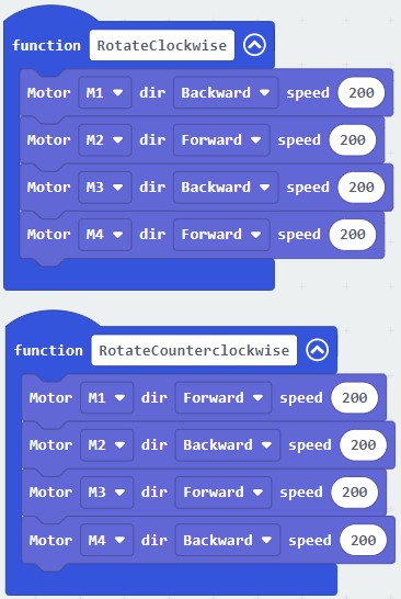
To make the car rotate clockwise, each wheel should move according to the arrow direction of the above picture: M1 and M3 move backward, M2 and M4 move forward.
Rotate counterclockwise
To make the car rotate counterclockwise, each wheel should move according to the arrow direction of the above picture: M1 and M3 move forward, M2 and M4 move backward.
Start to program
Create a new project “RotaryMotion”:

We need to load the Funbit extension library of the car:
https://github.com/szhengjiaanv/pxt-Funbit
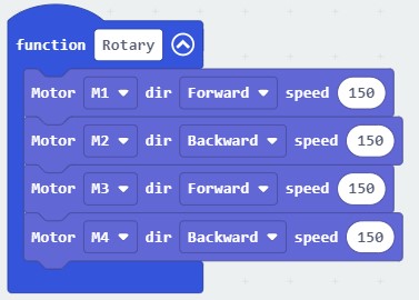
Here we will use function:
Click “Advanced” and then appear the following page:

We can create functions in “Functions”, and then call these functions. We should create functions of “RotateClockwise” and “RotateCounterclockwise”.

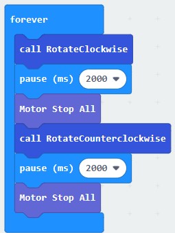
In “forever”, we call functions of “RotateClockwise” and “RotateCounterclockwise”.
The written program “RotaryMotion.hex” can be imported directly.
http://wiki.haljia.com/download/microbit/smartrobot_mecanum/RotaryMotion.hex
Start to test
Download the program to micro:bit board and then turn on the car.
The smart car rotates all the time following the direction of “RotateClockwise” and “RotateCounterclockwise”.
Obstacle Avoidance Motion of Smart Car
Learning content
1.Learn about the obstacle avoidance principle of the car and the use of ultrasonic ranging module and servo.
2.Learn to create and call functions.
3.Learn the programming of the car’s obstacle avoidance motion of ultrasonic ranging module.
Basic introduction of obstacle avoidance
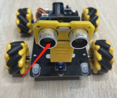
The arrow points to the ultrasonic ranging module, which can judge the distance to obstacle in front of the car.
The car can avoid obstacle by judging the obstacle’s distance to the car and then changing the motion direction of the car.
The trig port of ultrasonic ranging module links to the P14 port of the micro:bit board. And the echo port links to the P15 port of the micro:bit board.
Through the rotation of the servo, the ultrasonic module can rotate to judge the distance to the left and right obstacle.
Start to program
Create a new project “ObstacleAvoidance”:
We need to load the Funbit extension library of the car:
https://github.com/szhengjiaanv/pxt-Funbit
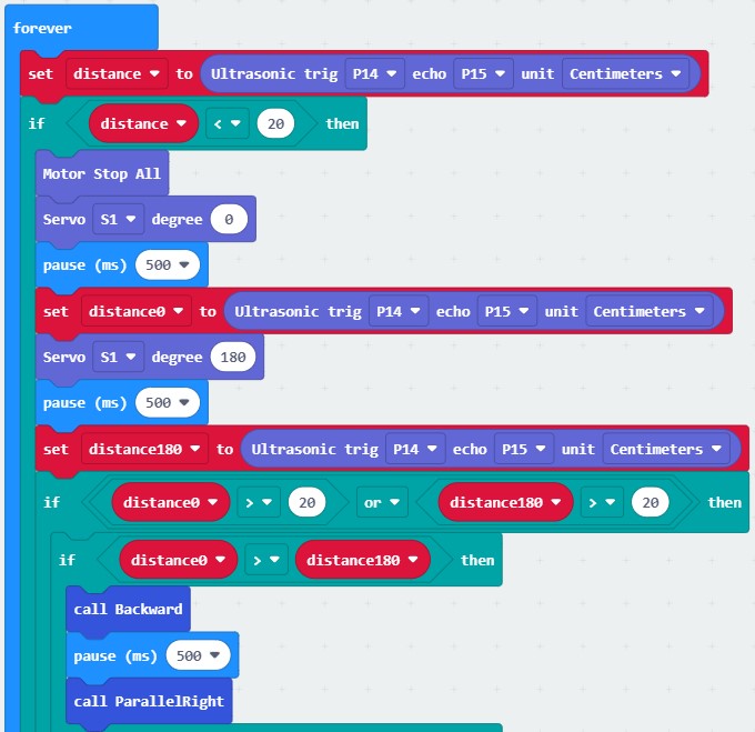
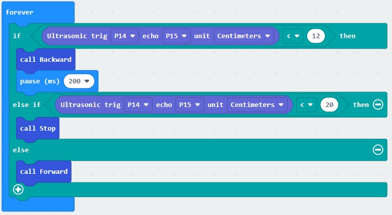
The trig port of ultrasonic ranging module links to the P14 port of the micro:bit board. And the echo port links to the P15 port of the micro:bit board.
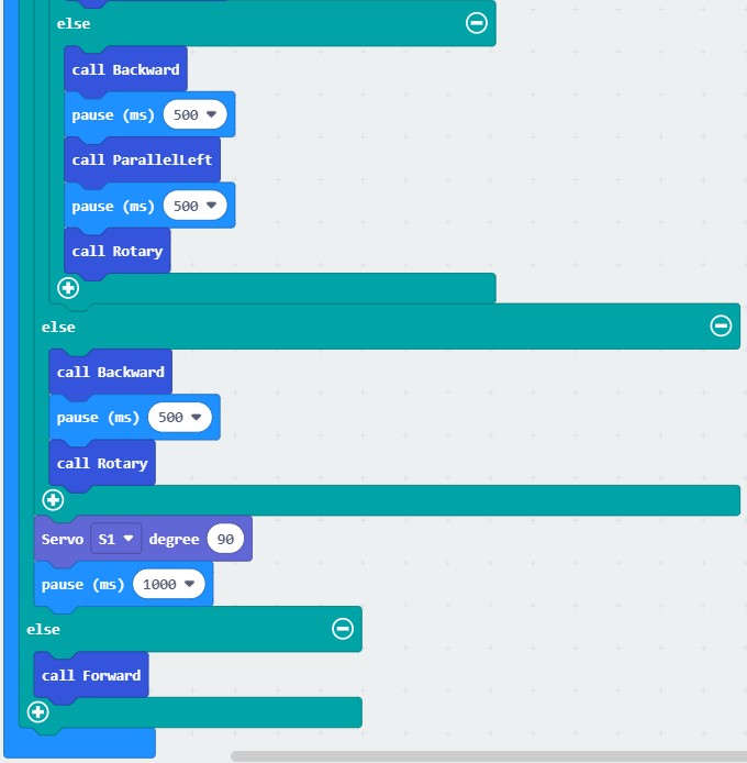
With the two ports, we can know the distance to the front obstacle when programming. If the distance is over 20cm, the car will move forward; if it’s less than 20cm, we can use ranging module to judge which side is farther from the obstacle through the servo’s rotation: turn left or turn right. The car will move toward the direction which is farther from obstacle. And then the car pans left or pans right after backing off.
Here we will use function:
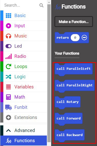
Click “Advanced” and then appear the following page:

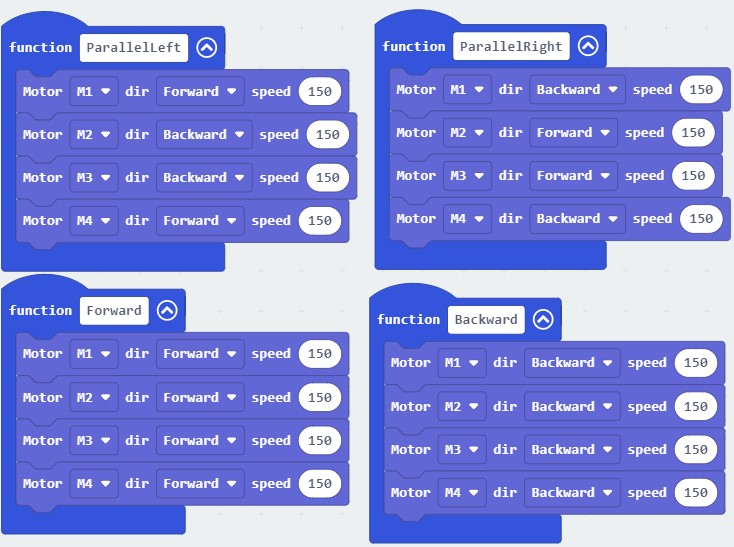
We can create functions in “Functions”, and then call these functions. We should create functions of “Forward”, “Backward”, “ParallelLeft”, “ParallelRight” and “Rotary”.
The written program “ObstacleAvoidance.hex” can be imported directly.
http://wiki.haljia.com/download/microbit/smartrobot_mecanum/ObstacleAvoidance.hex
Click “Download” to download the program to micro:bit board.
Start to test
Download the program to micro:bit board and then turn on the car.

When the car is far away from the obstacle, it keeps moving forward, and when it is near the obstacle, it immediately backs off, pans left, pans right, and rotates, and then moves forward after bypassing the obstacle.
Python Programming
Build Python Programming Environment
Download and installation of Mu Python
There we will introduce Mu Python, a tool of programming. Open the following link in browser:
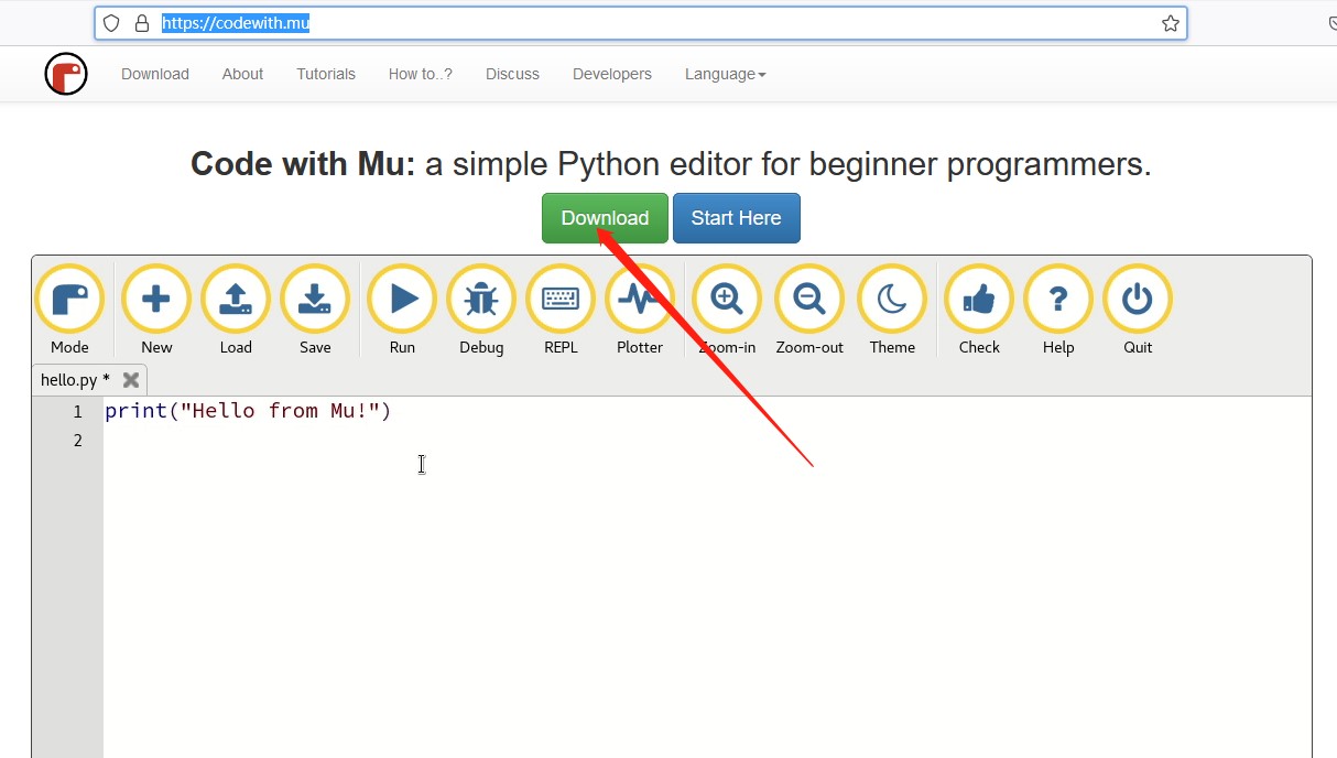
Click “Download” to enter the following page:
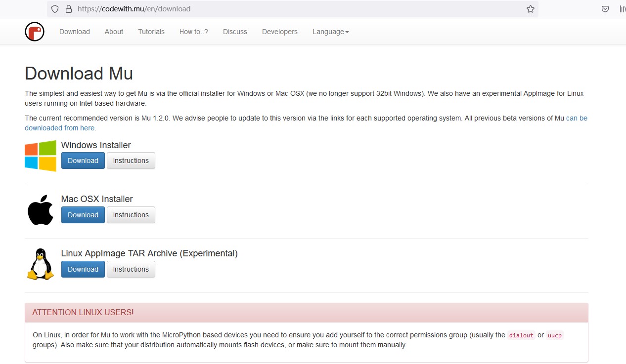
Choose relative operating system to download the Mu software, and then install it.
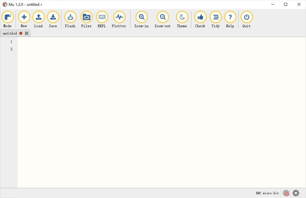
Or we can directly execute the file MuEditor-win64-1.2.0.msi to install and then enter the following programming environment:
http://wiki2.haljia.com/download/microbit/smartrobot/MuEditor-win64-1.2.0.msi
After finishing installation, it will show the following icon:

Start Python
Click the icon to start Mu Python programming.

Click “Mode”:
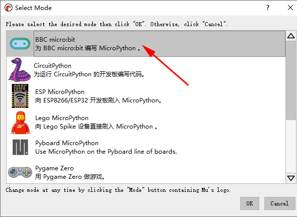
Choose BBC micro:bit.
The First Project
Learning content
1.There we will implement the display of number “1” in the screen of micro:bit board by programming;
2.Learn to save and load program.
Start to program
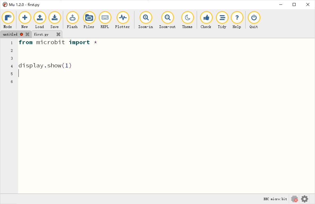
We will implement the display of number “1” in the screen of micro:bit board.
We write into our codes here:
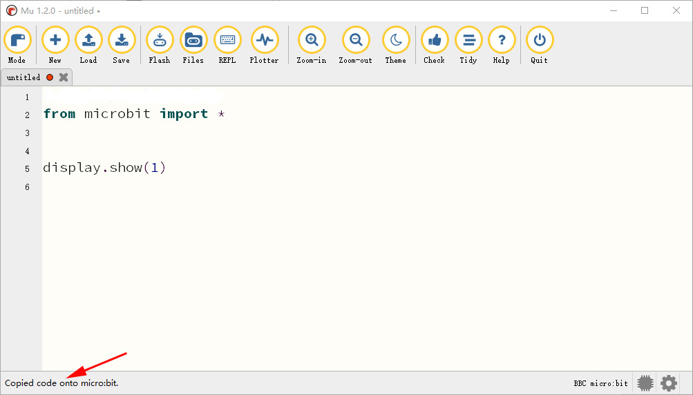
from microbit import *
display.show(1)

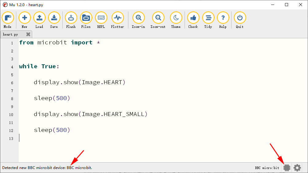
Check micro:bit connection
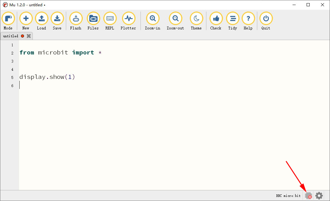
If the place the arrow points at displays red “x”, it shows that the micro:bit board doesn’t connect with computer. At this time, we should use the USB cable to connect the micro:bit board with computer. Then it will show the following picture:
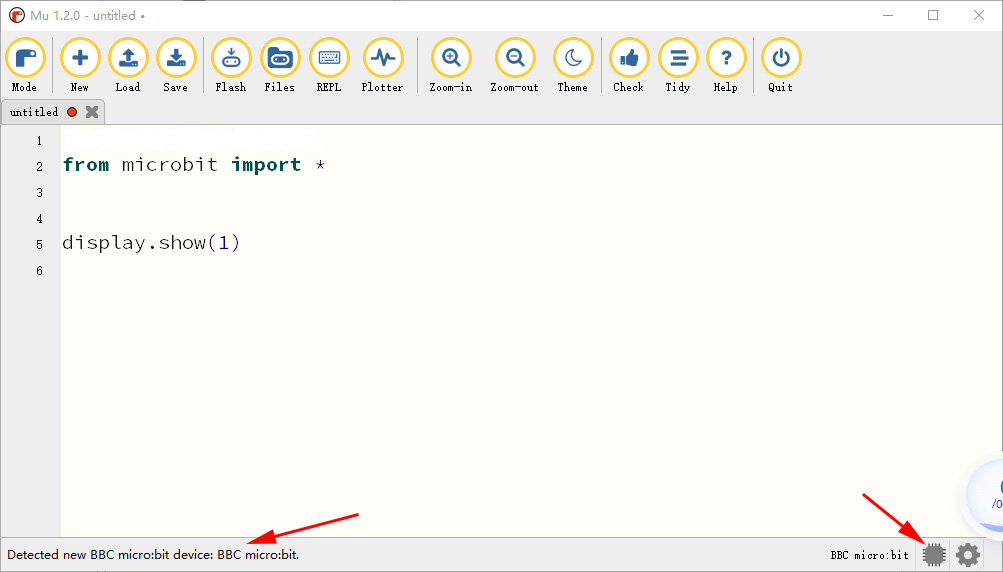
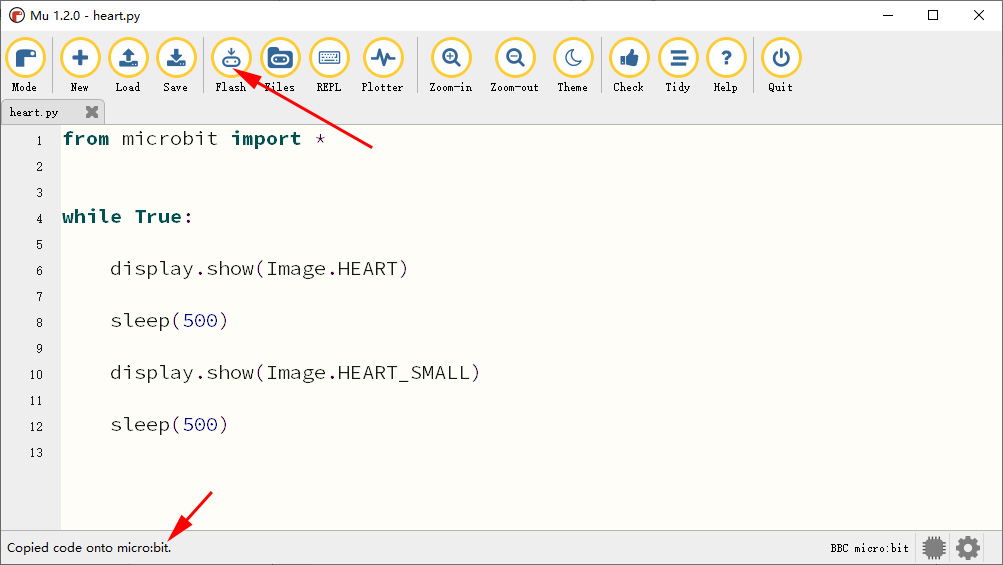
At this time, we can flash the program into the micro:bit board. Click “Flash” icon in the following picture and then the place the arrow points at will show: Copied code onto micro:bit.
Start to test
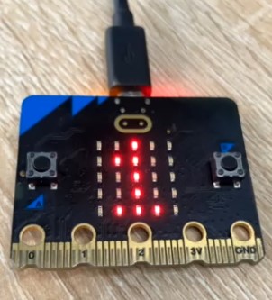
When the car is powered on, the screen of micro:bit will display number “1”. Then we have finished our first project successfully.
Save the program
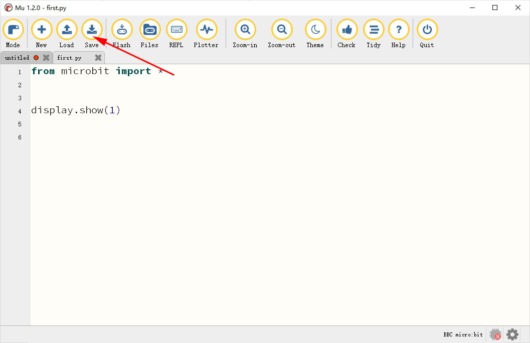
Click “Save” to save the program as "first.py".
http://wiki.haljia.com/download/microbit/smartrobot_mecanum/first.py
Load the program
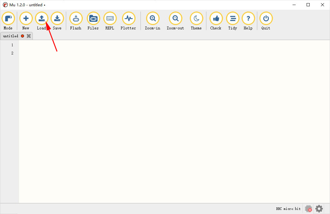
Click “Load” to load the saved program "first.py".
http://wiki.haljia.com/download/microbit/smartrobot_mecanum/first.py
After loading, appear the following page:
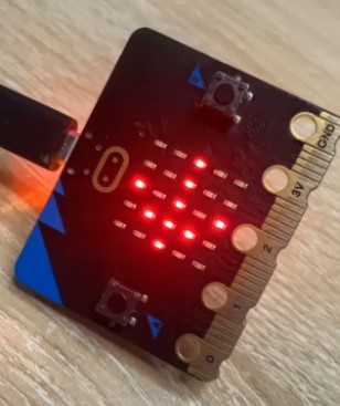
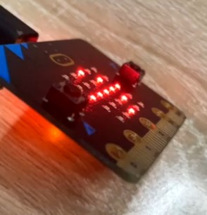
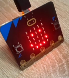
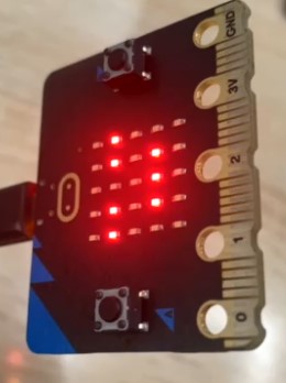
Display Large and Small Heart Image
Learning content
Here we will implement the display of large and small heart image in the screen of micro:bit board by Python programming.
Start to program
There program is a loop that large heart image and small heart image display 0.5 second respectively.

If the place the arrow points at displays “x”, it shows that the micro:bit board doesn’t connect with computer. At this time, we should use the USB cable to connect the micro:bit board with computer. Then it will show the following picture:
At this time, we can flash the program into the micro:bit board. Click “Flash” icon in the following picture and then the place the arrow points at will show: Copied code onto micro:bit.
Or we can load the written program “heart.py”.
http://wiki.haljia.com/download/microbit/smartrobot_mecanum/heart.py
Start to test
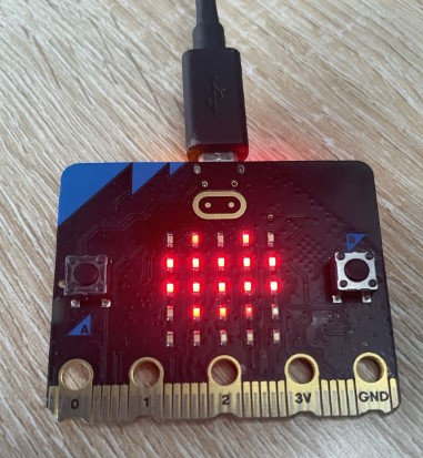
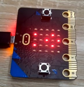
When micro:bit is powered on, the large heart image and small heart image are displayed cyclically.
Play Music
Learning content
There we use Python to implement music-playing in the buzzer of micro:bit board.
Start to program
There program is to play music score.
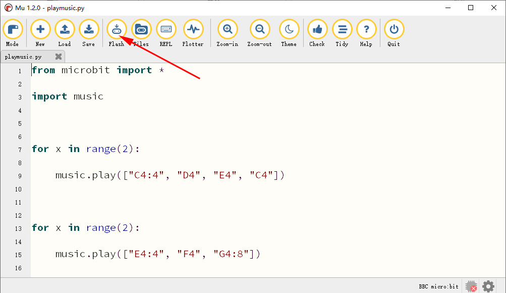
And then flash in the program.
Here we can also load the written program "playmusic.py".
http://wiki.haljia.com/download/microbit/smartrobot_mecanum/playmusic.py
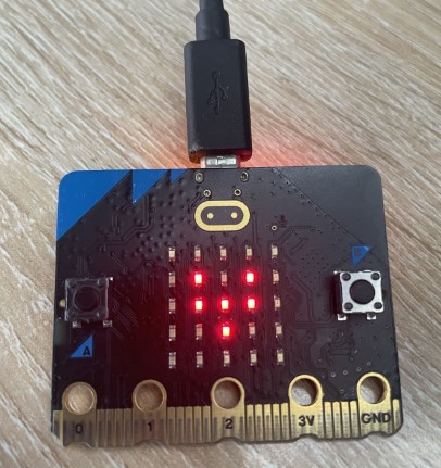
Start to test
After micro:bit is powered on, it will play the music of “Two Tigers Running Fast”.
Button and Touch
Learning content
Learn to program the button and touch.
Here we will implement a function of timekeeping to understand the programming of micro:bit’s button and touch. When we press the button A, it will display large and small heart image and start to measure time. When we press the button B, it will display the sleeping image and calculate the time interval since we have pressed the button A.
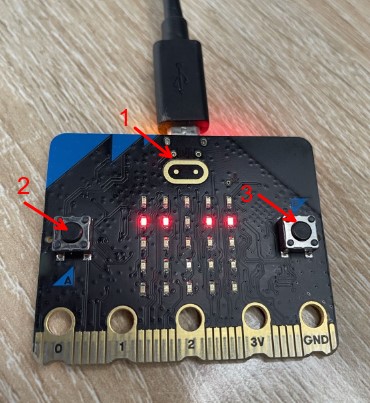
The arrow 1 points to touch logo, arrow 2 points to button A, and arrow 3 points to button B.
Start to program
Write into the following codes:
from microbit import *
time = 0
start = 0
running = False
while True:
if running:
display.show(Image.HEART)
sleep(300)
display.show(Image.HEART_SMALL)
sleep(300)
else:
display.show(Image.ASLEEP)
if button_a.was_pressed():
running = True
start = running_time()
if button_b.was_pressed():
if running:
time += running_time() - start
running = False
if pin_logo.is_touched():
if not running:
display.scroll(int(time/1000))
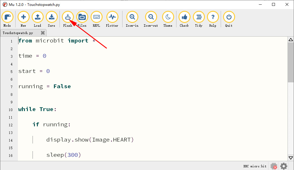
After finishing writing program, flash it into micro:bit.
Here we can also load the written program "Touchstopwatch.py".
http://wiki.haljia.com/download/microbit/smartrobot_mecanum/Touchstopwatch.py
Start to test
After powered on, the micro:bit will display the sleeping image.

After pressing button A, the large and small heart image blinks and it starts to measure time:

After some time, press button B and it will display sleeping image. At the same time, it is counting the time interval between pressing button A and B.
Press the touch icon and it will display time interval. (unit: second)
Acceleration Sensor
Learning content
Learn the programming of built-in accelerometer sensor and can judge whether there is vibration and the direction of movement: up, down, left, and right.
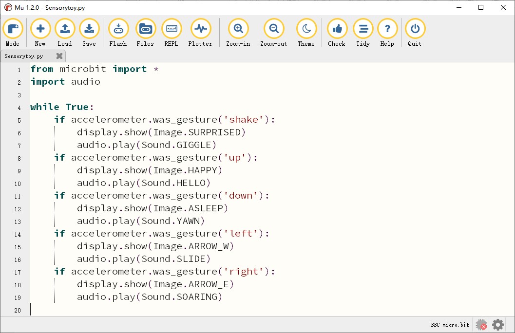
Start to program
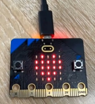
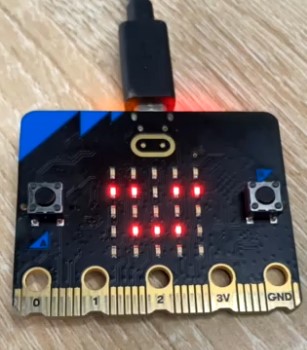
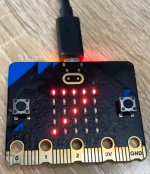
There program is a loop. When we shake the built-in speaker of micro:bit, it will play the sound of giggle and display a smile in the LED screen. Lean the micro:bit in different directions (up, down, left, and right) will show corresponding image and sound.
Flash the program into micro:bit.
Here we can also load the written program "Sensorytoy.py".
http://wiki.haljia.com/download/microbit/smartrobot_mecanum/Sensorytoy.py
Start to test
Lean left will display the following image and sound:
Lean right will display the following image and sound:
Lean down will display the following smile image and sound:
Lean up will display the following sleeping image and sound:
When shaking the micro:bit, it will display the following image:
Dazzling Light
Learning content
1.Learn to use neopixel library to program the dazzling light in order to display various colors;
2.Learn to use random library to generate random number.
Introduction of LED light
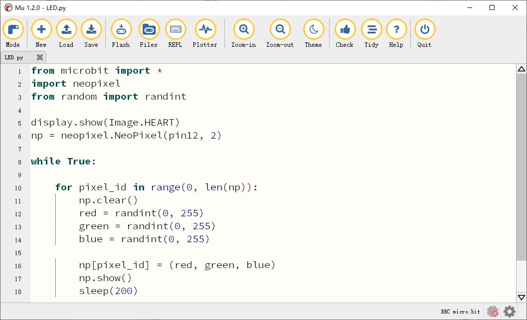
Our two LED lights link to P12 port of micro:bit. There we program to make the two LED lights spark random color.
Start to program
There we introduce neopixel library:
Flash the program into micro:bit.
We can also load the written program “LED.py”.
http://wiki.haljia.com/download/microbit/smartrobot_mecanum/LED.py
Start to test


When the car is powered on, the two dazzling lights spark in turn and change colors randomly.
Ultrasonic Ranging
Learning content
1.Learn about the use of ultrasonic ranging module.
2.Learn to program the ultrasonic module to measure the distance.
Introduction of ultrasonic module

The arrow points to the ultrasonic ranging module, which can judge the distance to front object.
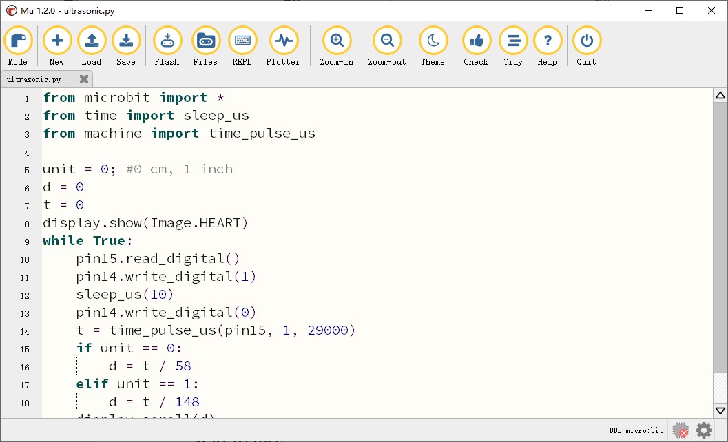
The trig port of ultrasonic ranging module connects with P14 port of Micro:bit board, and the echo port connects with P15 port of Micro:bit board.
Start to program
Here we write into codes:
Flash program into micro:bit.
We can also load the written program “ultrasonic.py”.
http://wiki.haljia.com/download/microbit/smartrobot_mecanum/ultrasonic.py
Start to test
When the car is powered on, the number displays in the micro:bit board is the distance of front object.
Support
If you need technical support or have any question, please feel free to contact us. We are sure to reply to you within 1~2 working days. When you contact us, don’t forget to attach your order number and shopping platform.
Working Time: 9 AM – 6:30 PM (Monday to Friday)
EMAIL: Support@HALJIA.com